Download
1 / 36
360 likes | 587 Vues
Suomi NPP VIIRS On-Orbit Geometric Performance. NASA VIIRS Calibration Support Team (VCST) Geometric Calibration Group Robert E. Wolfe, NASA/GSFC Code 619 Mash Nishihama, Sigma Space/GSFC Guoqing (Gary) Lin, Innovim /GSFC Krishna P. Tewari, Innovim /GSFC a nd

E N D
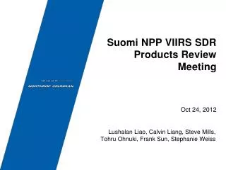
Suomi NPP VIIRS On-Orbit Geometric Performance NASA VIIRS Calibration Support Team (VCST) Geometric Calibration Group Robert E. Wolfe, NASA/GSFC Code 619 Mash Nishihama, Sigma Space/GSFC Guoqing (Gary) Lin, Innovim/GSFC Krishna P. Tewari, Innovim/GSFC and Northrop Grumman Aerospace Systems (NGAS) Lushalan Liao, Stephanie Weiss Suomi NPP VIIRS SDR Product Review (Provisional Release) October 24, 2012
Outline • Introduction and objectives • I and M Band geolocation (DNB later in NGAS section) • Orbit/attitude • Encoders characteristics • Band-to-band co-registration • Spatial response • Day Night Band (DNB) Terrain correction • Issues, challenges and concerns • Summary Wolfe et. al., Oct. 24, 2012
NICSE/GEO Objectives • VIIRS geometric (GEO) calibration and characterization of Sensor Data Record (SDR/GEO) • Geolocation assessment and geolocation accuracy improvements (Look-Up-Table (LUT) updates) • Assessment of other geometric related topics • Rotating Telescope Assembly (RTA) and Half Angle Mirror (HAM) encoder characteristics • Band-to-band co-registration (BBR) • Sensor spatial response parameters – Line Spread Function (LSF) derived Field of View (FOV), Modulation Transfer Function (MTF) and Horizontal Spatial Resolution (HSR) • Satellite orbit ephemeris and attitude • Collaboration with other Teams in overall SDR characterization, calibration, validation, and anomaly resolution (See DRs in the Backup) Wolfe et. al., Oct. 24, 2012
VIIRS SDR/GEO Tasks Status and Plans Wolfe and SDR/GEO Team was assigned as the lead for 11 of 58 VIIRS SDR Cal/Val tasks defined in the OPSCON Wolfe et. al., Oct. 24, 2012
VIIRS Geometry/Pointing Summary • Overall VIIRS Geometry is good • S/C Attitude control system and on-board GPS ephemeris performance currently meeting VIIRS needs • SDR/GEO LUT update based on on-orbit control point residual analysis is in IDPS operations (2/23 for M&I bands, 3/30 for DNB by NG) • RTA and HAM Encoders are performing well Wolfe et. al., Oct. 24, 2012
Control Point Matching (CPM) Program Over 1200 globally distributed Ground Control Point (GCP) chips of Landsat red band (0.64 µm) 30 m nadir resolution Sample Landsat-5 TM GCP chip (Appleton, Wisconsin) • VIIRS detector point spread function (PSF), including effects of aggregation and bow-tie deletion, is used to simulate VIIRS band I1 (0.64 µm) scenes from Ground Control Point (GCP) chips (DNB uses similar method but limited to coastal GCPs) • Cross-correlation is performed between the simulated and actual I1 scenes • Shift the simulated scenes to get location of maximum cross correlation coefficients CPM program runs in the NASA SDS Land PEATE Wolfe et. al., Oct. 24, 2012
VIIRS Residual Trend Wolfe et. al., Oct. 24, 2012
VIIRS Scan Angle Residuals Wolfe et. al., Oct. 24, 2012
Bias correction (fine tuning) • Bias correction model can currently examine 15 geometric parameters: • Instrument to spacecraft alignment (inst_roll, inst_pitch, inst_yaw) • HAM parameters (alpha_wedge, beta_wedge, gamma_axis) • RTA to instrument alignment (tele_roll, tele_pitch, tele_yaw) • HAM to instrument alignment (ham_roll, ham_pitch, ham_yaw) • Magnification (mag_tele), focal length (focal_len) and scan rate (samp_time) • Computed least-squares solution using a pyramid sequential maximum decent search method with different combinations of the first 12 parameters (all except for magnification, focal length and scan rate) • Found first nine parameters performed well, with additional three parameters (ham_roll, ham_pitch, ham_yaw) not significantly changing results • Parameters: current / best fit (arcsec) – large change in bold font inst_roll = -227.3 / -227.3 inst_pitch =153.2 / 68.6inst_yaw= 95.4 / 95.4 alpha_wedge = 3.9 / 4.1 beta_wedge= 9.5/ -125.2gamma_axis= -6.0 / -6.2 tele_roll= 0.0 / -5.4tele_pitch= 0.0 / 75.5tele_yaw= 0.0 / -13.4 ham_roll= 0.0 / 0.0 ham_pitch= 0.0 / 0.0ham_yaw= 0.0 / 0.0 • Following slides show this optimal solution • Additional analysis is needed to understand unexpected change in HAM beta wedge angle (may need to be excluded from solution) and solution stability Wolfe et. al., Oct. 24, 2012
VIIRS Residual Trend – Corrected • Corrected (poly fit) • Current (poly fit) • Corrected (poly fit) • Current (poly fit) Wolfe et. al., Oct. 24, 2012
VIIRS Scan Angle Residuals – Corrected • Corrected (poly fit) • Current (poly fit) • Corrected (poly fit) • Current (poly fit) Wolfe et. al., Oct. 24, 2012
Bias correction • Nadir equivalent accuracy (RMSE – Root Mean Square Error) • 201 data-days, average of 137 CP residuals per day (after filtering) • After VIIRS I/M-band LUT update on Feb. 23, 2012 • 16-day test will be performed with Land PEATE to verify new parameters (after further refinement) preform as expected • Delivery of new LUT with additional DNB LUT changes (see NGAS charts) will be made after technical review (~ Nov. 2012 timeframe) Wolfe et. al., Oct. 24, 2012
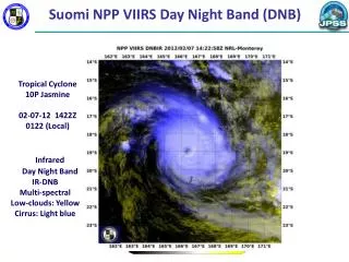
Equator-crossing local time • 13:24:46 on 11/17/2011 • Leap Second • Local time at ascending node (LTAN) slowly oscillates. • West-most point is ~13:23:00, ~ 50 km from Nov. 17, 2011. • Orbit is expected to drift eastward after October, 2012. • Leap Second was added on June 30, 2012 Wolfe et. al., Oct. 24, 2012
Task GEO2: Encoder Analysis results from telemetry scan PGE running on NSIPS • Half-angle Mirror (HAM) and Rotating Telescope Assembly (RTA) Encoder Data is valid and stable most of the time • Scan rate appears unchanged since ground testing • Telescope 3.5311 rad/sec, long term deviation approximately 1e-7 rad/sec • HAM 1.7655 rad/sec, long term deviation approximately 8e-7 rad/sec • Power Spectral Densities (PSDs) are similar to pre-vibe • Exceptions during sync-loss events (see charts following) when all encoder characteristics behave anomalously • Current understanding of scan mechanism supports provisional status of SDR’s. Correct flagging of products during scan sync-loss will be implemented for Mx6.5 which will enable users to avoid invalid SDRs when employing the data for operational use and scientific investigation. • 0.0 1.9 3.8 5.7 7.6 9.5 11.4 • 0.0 1.9 3.8 5.7 7.6 9.5 11.4 • months since 2011-11-10 • months since 2011-11-10 Wolfe et. al., Oct. 24, 2012
Stable scan mechanisms • Non-linear HAM (blue) and RTA (red) • Synchronization Error Scan mechanisms are stable (and consistent with pre-launch data) as indicated by HAM and RTA encoder analysis Rare exception: scan synchronization loss events (next chart) February 2012 • HAM PSD • RTA PSD • Non-linear HAM (blue) and RTA (red) • Synchronization Error October 2012 • HAM PSD • RTA PSD Wolfe et. al., Oct. 24, 2012
Synchronization loss • 1. Major event example • Average (2 * HAM – RTA) • Average RTA scan rate Two types of sync loss Major events (~60 scans) involve RTA disturbances that resulted in HAM speeding up. Minor events (7-8 scans) involve HAM disturbances only. • RTA and 2 * HAM scan rates • Average HAM scan rate) • 2. Minor event example • Average (2 * HAM – RTA) • Average RTA scan rate Currently there is no ‘fix’ for this problem. Software changes will flag this problem and fill both SDR and GEO for affected scans. • RTA and 2 * HAM scan rates • Average HAM scan rate) Wolfe et. al., Oct. 24, 2012
VIIRS on-orbit Spatial Response– preliminary verification in the scan direction Lake Pontchartrain Causeway scan direction Band I2 • Lake Pontchartrain Causeway provides a line source with a slight angle for creating LSFs using modified Lorentzian fit • Additional analysis of other targets is being performed VIIRS Image Wolfe et. al., Oct. 24, 2012
Task IMG4: Image Quality • Objective • Evaluate spatial characteristics (HSR for I-bands, MTF for M-bands) of the VIIRS instrument in operational condition. • Spatial characteristics meet criteria for provisional maturity. Estimates of HSR for I-bands indicate that the optical system is performing as expected. They will meet calibrated and validated maturity once more statistics is accumulated and detailed study of M-band is also performed. Wolfe et. al., Oct. 24, 2012
Scene types used in image quality evaluation Ice/water edges are ideal for reflective bands. However, model correction for orientation is necessary. Land/water and ice/water edges are utilized for emissive bands but are not ideal. Degraded results expected. Wolfe et. al., Oct. 24, 2012
VIIRS Band to Band Registration (BBR) Scan (M-sampintvl) LWIR VisNIR S/MWIR M1 Track (M-sampintvl) • Band average BBR (wrt. Band I1) compares well to prelaunch performance • M/LWIR bands are saturated by moon – further analysis being performed • Work is on-going (five Vis/NIR and four S/MWIR measurements so far) • Analyzing spectral effects on Lunar BBR Wolfe et. al., Oct. 24, 2012
ROLO telescope lunar data 1240 nm (M8) May 31, 2012 412 nm (M1) Feb. 3, 2012 1610 nm (M10/I3) May 31, 2012 650 nm (M7/I2) Feb. 3, 2012 • High resolution lunar data is being used to exam spectral effects on VIIRS lunar BBR • High resolution lunar data may also be used to verify VIIRS spatial performance Data courtesy of Tom Stone (USGS) Wolfe et. al., Oct. 24, 2012
Band-to-Band Registration (BBR) with edge analysis and Mutual Information Maximization • Objective • Evaluate BBR of the VIIRS instrument in operational condition and recommend timing adjustments between focal planes on as needed. • Two alternative approaches to derive BBR between bands: • Edge analysis • Mutual Information Maximization • BBR between FPA’s evaluated by studying I1, I3, I4 and I5 which are located on three different focal planes. BBR between different stages of DNB was also evaluated. • BBR meets criteria for provisional maturity. The focal planes are well registered to each other and do not require timing adjustment. The registration between DNB stages are better than 5%. BBR will meet calibrated and validated maturity when M-bands are included in the evaluation to study the effect of plate scale change. Negative numbers means the second band leads the first band. For example, edge analysis indicates I5 sees a particular feature at 7% of I-band HSI before I1 does. Wolfe et. al., Oct. 24, 2012
BBR trend and associated uncertainty using Mutual Information Maximization (MIM) • Scan direction registration to band I1 Data from Feb 2012 to July 2012 indicates stable BBR between focal planes with minor upward trend in I1/I4 track registration. All registration offsets are less than 10% of an I-band sampling interval, consistent with pre-launch measurements. • Track direction registration to band I1 Wolfe et. al., Oct. 24, 2012
DNB Geolocation w/ Terrain Correction (TC) +31.7o M-Band -31.7o -44.9o Nadir +44.9o • Coding finished • Tested DNB terrain heights compare well with M-band terrain (in pixel coordinates). The white vertical lines delineate the boundaries of M-band aggregation zones and the corresponding scan angles for DNB. +31.7o DNB -31.7o -44.9o Nadir +44.9o 24 Wolfe et. al., Oct. 24, 2012
Verification of DNB TCed Geolocation • Start of Scan • DNB:11th – 16th samples, average height = 4199 m • M: 1st to 3rd samples, detectors 3-14, average height = 4064 m. Wolfe et. al., Oct. 24, 2012
Issues, Challenges and Concerns • DNB geolocation terrain corrected coding is completed. Expected to be in IDPS Mx6.5 (Jan. 2013). • RTA/HAM synchronization loss – switch from current Servo B side to A side • Software and LUTs updates are in place for switch • Software to identify and correctly handle sync losses are planned for Mx6.5 • Challenging in accurate estimate of on-orbit BBR for all band pairs, especially for those LWIR bands saturated by the moon – NGAS mutual information method and ROLO lunar model may help • Challenging in accurate spatial response characterization for all bands, especially LWIR bands – expect no significant change from pre-launch and no significant impacts on EDRs • Within orbit thermal correction is likely to be needed – code change required • Long-term Monitoring is needed for accurate geolocation – we are trending and fine tuning • Digital Elevation Model (DEM) and Land/Water (L/W) mask should be updated (see MODIS C6) • Geolocation accuracy near spacecraft maneuvers needs to be better understood and clearly identified • QA bytes/fields need detailed examination Wolfe et. al., Oct. 24, 2012
Concluding Remarks • VIIRS geometric performance is as expected • Geolocation I/M-band accuracy is sub-pixel after first on-orbit LUT update and fine tuning is underway • Encoder and scan time/period are nominal • Orbit and attitude are nominal • BBR for non-lunar-saturated bands looks good • VIIRS SDR/geometric performance maturity should be rated as Provisional Wolfe et. al., Oct. 24, 2012
Backup Wolfe et. al., Oct. 24, 2012
Geometric related DRs & Status Wolfe et. al., Oct. 24, 2012
Nominal orbit • Orbit nominal • Local time of ascending node (oscillating slowly) • Period: 101 min 30 sec; Inclination: 98.66º • Altitude: ~828 km over equator, ~840 km over n. Pole, ~855 km over s. pole, average 839 km above ellipsoidal earth surface Wolfe et. al., Oct. 24, 2012
Nominal attitude • Nominal attitude right after attitude subsystem tuning on Nov. 17, 2011 • Slow periodical variations: +/-15 arcsecorbital oscillation of roll and yaw; +/-3 arcsec of pitch oscillation every half orbit. • Attitude variations are tracked by geolocation software Wolfe et. al., Oct. 24, 2012
Encoder characterization Encoder residuals (non-linear motion) • The linear scan rate of telescope was 3.531 rad/sec on Nov 9, 2011. • The offset variation is consistent with pre-launch tests (more in NG slides) • Rotating Telescope Assembly (RTA) and Half Angle Mirror (HAM) encoder datasets had been erroneously swapped in the at-launch IDPS code. The error was corrected, as plotted here, and implemented in IDPS drop Mx5.1 on Dec 19, 2011. Angle Residuals: Deviation from linear trend for 1stScan (Granule 05:45 on Nov. 8, 2011, doy 312) Wolfe et. al., Oct. 24, 2012
Scan to scan start angle • Variations around -56.34º (used in the geolocation algorithm) • Magnitude ~ 16 arcsec, half of an I-band scan sampling interval • Data from one 48-scan (85-sec.) granule on data-day June 27, 2012 I-Sampling Interval ~ 800 m at Start of Scan Wolfe et. al., Oct. 24, 2012
Scan mechanisms are stable as indicated by encoder analysis Post-launch, encoder scan characteristics are stable and consistent with Pre-launch data except during scan synchronization loss events as indicated on the following charts. Wolfe et. al., Oct. 24, 2012
Synchronization loss (1/2) Two types of synchronization loss: short events (7-8 scans) that do not involve RTA and long events (13 scans) that involve both RTA and HAM. Encoder data indicate that the start of change in scan rate can occur at any point within a scan. This chart shows an example of SHORT event. Wolfe et. al., Oct. 24, 2012
Synchronization loss (2/2) Long events involve RTA disturbances that resulted in HAM speeding up for the duration such that at the end of the event, HAM has traveled 180 degrees more than it otherwise would have. Currently there is no ‘fix’ for this problem. Software changes (to be submitted by NGAS for Mx6.5) will flag this problem and fill both SDR and GEO for affected scans. Wolfe et. al., Oct. 24, 2012