Network Booting Upgrade Procedures Using Cabletron TFTP/BootP Services 2.0
150 likes | 280 Vues
This guide outlines the steps required to upgrade your PC via network booting using Cabletron TFTP/BootP Services 2.0. It covers essential preparations, including setting up the TFTP server and executing the upgrade file. Detailed instructions on entering MAC addresses, file paths, and IP addresses are provided, along with LED status indicators to help troubleshoot potential issues. Adhering to these procedures ensures a smooth upgrade experience while maintaining continuous operation of your network devices.

Network Booting Upgrade Procedures Using Cabletron TFTP/BootP Services 2.0
E N D
Presentation Transcript
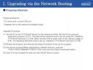
1. Upgrading via the Network Booting ■ Preparing Materials Preparing Materials -PC server with a wired LAN port -Upgrade file for the network booting(bin type) Upgrade Procedure 1) Set the PC to the TFTP/BootP Server for the network booting. Set the PC by using an application program for PC. This description explains how to set up using the ‘Cabletron TFTP/BootP Services 2.0 S/W. When another S/W is used, refer to the relevant usage of S/W. The following describes how to set up ‘Cabletron TFTP/BootP Services 2.0 S/W’. 2) Receive the program and execute the Setup procedure to set up the program. 3) Execute the program(When designating a default directory, execute ‘C:\TFTPBOOT\BIN\TFTPBOOT.EXE’) and click the [Start Download] button. 4) Enter IP of the installed PC and click the [BootP Server] button.
Enter the IP of installed PC and press the Enter key Press the Start Download button Press the BootP Server button 1. Upgrading via the Network Booting ■ Cabletron TFTP/BootP Services 2.0 S/W
1. Upgrading via the Network Booting ■ Cabletron TFTP/BootP Services 2.0 S/W • Enter the MAC address of AP where to receive the file from Enter the pathe and name of the file that AP will receive, or select the file by clicking the browser at the botton Enter the IP that AP is to be assigned Click the Update button
LED Name The number of B channels being communicated Function LED status of the LD1 Blue On Blue Off LED status of the LD2 Blue Blinking PWR Status of Power Supply Normal power supply No power supply - 0 Blue LED Off Blue LED Off One WLAN Operating status of wireless LAN Blue LED Blinking Periodically Normal operation of wireless LAN No operation of wireless LAN Blue LED Off Data being received and transmitted via wireless LAN Two Blue LED Off Blue LED Off LAN Operation status of LAN Normal operation of LAN No operation of LAN Data being received and transmitted via LAN Three Blue LED Off Blue LED Blinking Periodically WLI Connection status with the 8WLI Normally connected with the 8WLI card Not connected with the 8WLI card or calling Data being received and transmitted via the 8WLI card and the DASL line Four Blue LED Off Blue LED Off 2. WBS24(Combo) LED Status
LED Name Function Blue On Blue Off Blue Blinking PWR Status of Power Supply Normal power supply No power supply - WLAN Operating status of wireless LAN Normal operation of wireless LAN No operation of wireless LAN Data being received and transmitted via wireless LAN LAN Operation status of LAN Normal operation of LAN No operation of LAN Data being received and transmitted via LAN WLI System message transmission Normally connected with the 8WLI card Not connected with the 8WLI card System Data being transmitted to the System( period : 5sec ) 2. WBS24(Basic) LED Status
POWER ON - Verify the system power - Verify the 8WLI status, or 8WLI connection line NO PWR LED ON YES - If the same status continues after resetting two or three times, the flash memory image is damaged. - Upgrade via the network. YES The other LEDs except the PWR LED blink periodically. NO The LD2 LED blinks continuouslyON NO - Verify the MMC setting and values YES LAN LED ON (BLINK) WLI LED ON WLAN LED ON (BLINK) NO YES YES NO NO Operation fault of the LAN Verify the LAN line Operation fault of the WLAN Verify the PCMCIA card Not connected with the 8WLI . Booting completing and online status 2. The troubleshooting steps according to the LED status
3. Status Inquiry via a Web Browser ■ Inquiry of Config & Status
3. Status Inquiry via a Web Browser ■Inquiry of Config & Status Status items are shown below. Up-Time : the passed time after booting Booting Time : the final time of WBS24 booting Version : Information on the WBS24 version DASL Status : Connection status with the 8WLI Deactive : Not activated status of the DASL line Active(Not Config) : DASL line is activated, and the initialized message is not received from the system. Active(Config OK) : DASL line is activated, and the initialized message is received from the system. B-channel Status : the number of traffics being in use at present Associated Nodes : Unavailable at present
3. Status Inquiry via a Web Browser ■ Restarting WBS24
3. Status Inquiry via a Web Browser ■ Inquiry screen of Wilress LAN statistics
3. Status Inquiry via a Web Browser ■ Inquiry screen of the Ethernet statistics
4. Connecting the Console Terminal ■ Connecting the Console Terminal • 1) Execute the Tera terminal program • 2) Select the <Setup><Serial Port> from the new window • Bits per second: 19200 • Stop bit: 1 • Data bit: 8 • Parity bit: none • Flow control: none • 3) Login/Logout • Login:wlan • Password: **** <- wlan • Login successful • --> user logout • 4) Enter CLI(Console Line Interface) • --> co en • Switching from CLI to console mode - type 'exit' to return • 165.213.110.103>exit • -->
4. Using the Console Terminal ■ Using the Console Terminal Version 정보 165.213.110.103> version WBS24 version: 2004.01.02 V01.28 22:00 BSP: WBS24 BSP v1.0 (ISOS 8.2) CSP: He100/2xx CSP v2.3 (ISOS 8.2) Help 165.213.110.103> help Commands are: apset bridge buffer bun chips config db dnsclient dnsrelay dw event flashfs fm im ip ipstack isfs led pdhcpc restart rom snmp test uptime version wb webserver wlan wpa ww '.' repeats the last command Type 'help all' or 'help <command>' for more details Enter Sub menu 165.213.110.103>apset 165.213.110.103 apset > home 165.213.110.103>
4. Using the Console Terminal ■ Using the Console Terminal Current Status 165.213.110.103 apset> status ============ Configuration Display ============ WBS24 BASIC WLI ID ID = 3 WBS ID ID = 24 Primary IP (ip1) = 165.213.110.103 Primary IP Mask (sub1) = 255.255.255.0 Secondary IP (ip2) = 10.10.10.10 Secondary IP Mask (sub2) = 255.255.255.0 Gateway IP (gw) = 165.213.110.1 DNS1 IP (dns1) = 0.0.0.0 DNS2 IP (dns2) = 0.0.0.0 ESS ID (essid) = 987654 Assigned RF Channel (rfch) = 3 Wep Enable (wepenable) = disabled Wep Key (128 bit) (wepkey) = 00-00-00-00-00-00-00-00-00-00-00-00-00 SYSTEM IP (MCP) = 165.213.110.101 SYSTEM NETMASK (MCP) = 255.255.255.255 SYSTEM GateWay (MCP) = 165.213.110.1 SYSTEM MAC (MCP) = 0- 0-f0-3a-10-dc PDHCP CLIENT ENABLE 0 {1:disabled, 0:enable} Change Basic WBS24 ENABLE 0 {1:disabled, 0:enable} Qos Setting 1 {0:disabled, 1:enable}