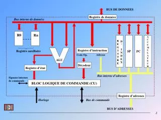
SCHEMA DE COMMANDE
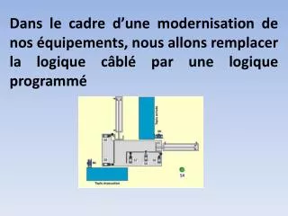
Dans le cadre d’une modernisation de nos équipements, nous allons remplacer la logique câblé par une logique programmé . Nous utiliserons cette partie de câblage pour l’alimentation des sorties de l’automate.

SCHEMA DE COMMANDE
E N D
Presentation Transcript
Dans le cadre d’une modernisation de nos équipements, nous allons remplacer la logique câblé par une logique programmé
Nous utiliserons cette partie de câblage pour l’alimentation des sorties de l’automate La logique câblée sera remplacé par une logique programmé par le biais d’un automate TSX 17-20 SCHEMA DE COMMANDE
AFFECTATION DES ENTREES SORTIES NON CABLE SUR L’AUTOMATE M1 Moteur asynchrone triphasé
AFFECTATION DES ENTREES SORTIES NON CABLE SUR L’AUTOMATE M2 Moteur asynchrone triphasé
AFFECTATION DES ENTREES SORTIES CABLE SUR L’AUTOMATE EN SORTIE KM1 Contacteur de puissance KM1
AFFECTATION DES ENTREES SORTIES CABLE SUR L’AUTOMATE EN SORTIE KM2 Contacteur de puissance KM1 KM2
AFFECTATION DES ENTREES SORTIES NONCABLE SUR L’AUTOMATE KM1 KM2
AFFECTATION DES ENTREES SORTIES NON CABLE SUR L’AUTOMATE KM1 KM2
AFFECTATION DES ENTREES SORTIES CABLE SUR L’AUTOMATE EN SORTIE KM1 KM2 1V14 2V14
AFFECTATION DES ENTREES SORTIES CABLE SUR L’AUTOMATE EN ENTREE S5 S6 S7 S8 et S9 capteur de position S5 KM1 S6 KM2 S7 1V14 2V14 S8 S9
AFFECTATION DES ENTREES SORTIES L’AFFECTATION DES ENTREES / SORTIES ETANT FAITE ON PEUT ALORS REALISER LE SCHEMA DE CABLAGE DE L’AUTOMATE S5 KM1 S6 KM2 S7 1V14 2V14 S8 S9
AFFECTATION DES ENTREES SORTIES L’AFFECTATION DES ENTREES / SORTIES ETANT FAITE ON PEUT ALORS REALISER LE SCHEMA DE CABLAGE DE L’AUTOMATE
SCHEMA DES E/S DE L’AUTOMATE 24v ~ 220V
SCHEMA DE COMMANDE Bobine du contacteur de puissance utilisé pour l’alimentation de l’A.P.I
SCHEMA DE PUISSANCE ALIMENTATION 24V~ CIRCUIT COMMANDE ALIMENTATION 220V A.P.I.