Electric Currents
Electric Currents. Topic 5 These notes were typed in association with Physics for use with the IB Diploma Programme by Michael Dickinson. Electric Circuits. 5.2.1 Define electromotive force ( emf )


Electric Currents
E N D
Presentation Transcript
Electric Currents Topic 5 These notes were typed in association with Physics for use with the IB Diploma Programme by Michael Dickinson
Electric Circuits 5.2.1 Define electromotive force (emf) IB Definition: electromotive Force(emf) – electromotive force is defined as the potential difference across the terminals of a source of electricity when there is no current flowing(open circuit p.d.) Example: Connect a voltmeter across a sourse of electricity(a AA battery). It will show the available potential difference(voltage). For the AA battery it will read 1.5V. Now add a the battery to a circuit, maybe a light bulb and the voltmeter reads slightly lover, possible 1.3V The term “force” is a misnomer. Measuered in Volts, symbol ε Called EMF
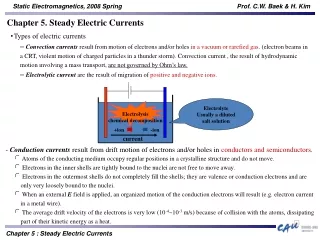
Electric Circuits 5.2.2 Describe the concept of internal resistance. So what happened to these “lost volts”? If the circuit is allowed to run for some time, the batter will heat up. This loss of energy in the battery is due to the “INTERNAL RESISTANCE” within the battery itself. ***Draw Internal resistance circuit*** Battery has internal resistance, r, and bulb with resistance, R, emf = terminal voltage + “lost volts” ε = Vterm + Vlost ε = IR + Ir 1.5V = 1.3V + 0.2V All electrical sources, power supplies, generators etc. have internal resistance
Electric Circuits 5.2.2 Describe the concept of internal resistance. IB Formula: ε = I(R + r) Practice 9 The open circuit terminal voltage of a battery is measured to be 9.0V. When connected to a light bulb, the voltage is seen to drop to 8.6V. If the current flowing in the circuit is measured at 0.02A, calculate the internal resistance of the battery. Answer: 20Ω
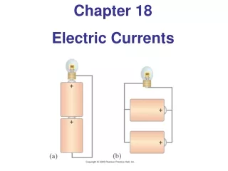
Electric Circuits 5.2.3 Apply the equations for resistors in series and in parallel. ***See Diagram on board*** Series Circuits • Current flowing is the same at all points • Potential difference across the terminals of the source of emf is = to the sum of the individual components in the external circuit. • Vtotal = V1 + V2 + V3 …. since V = IR • IRtotal= IR1+ IR2+ IR3…. • IRtotal = I(R1+ R2+ R3….) • Rtotal = R1 + R2 + R3 ….
Electric Circuits 5.2.3 Apply the equations for resistors in series and in parallel. ***See Diagram on board*** Parallel Circuits • The potential difference(voltage) across each branch of the circuit is equal • The total current entering a junction is equal to the total current leaving the junction. • Itotal = I1 + I2 + I3 …. since I = V/R • V/Rtotal= V/R1+ V/R2+ V/R3…. • V/Rtotal= V(1/R1+ 1/R2+ 1/R3….) • 1/Rtotal = 1/R1 + 1/R2 + 1/R3 ….
Electric Circuits 5.2.3 Apply the equations for resistors in series and in parallel. IB Physics Formula: Resistors in series • Rtotal = R1 + R2 + R3 …. Resistors in parallel • 1/Rtotal = 1/R1 + 1/R2 + 1/R3 …. • Non-IB formula worth remembering Product over sum - parallel • Rtotal = (R1 x R2)/(R1 + R2)
Electric Circuits Problem 10 Three resistors are connected in series. Their values are 2Ω, 4Ω and 6Ω. Calculate their combined resistance. Answer: 12Ω Problem 11 Three resistors are connected in parallel. There values are 20Ω, 30Ω and 40Ω. Calculate their combined resistance. Answer: 9.23Ω Problem 12 Two resistors are combined in parallel. There values are 6Ω and 3Ω. Calculate their combined resistance. Answer: 2Ω
Electric Circuits 5.2.4 Draw circuit diagrams
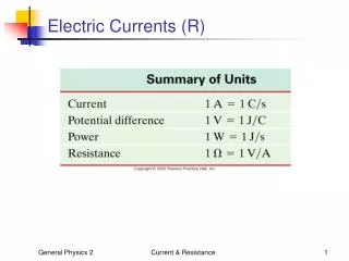
Electric Circuits 5.2.5 Describe the use of ideal ammeters and ideal voltmeters. Ammeter Measures amount of current flowing in a circuit. Connected IN SERIES with the components in the circuit. Should have low resistance. Voltmeter Measures amount of potential difference across an electrical component. Connected IN PARALLEL with the components in the circuit Should have high resistance.
Electric Circuits 5.2.6 Describe a potential divider Resistors in series split the voltage amongst the components in the circuit. Example: Two identical light bulbs with resistance, R, are connected to a 9.0V battery. The available voltage would be divided so each filament received 4.5V.If there were three then each bulb would receive 3V. If they have different resistance then the available voltage is divided up proportionally among the components.
Electric Circuits 5.2.6 Describe a potential divider
Electric Circuits 5.2.6 Describe a potential divider Total available potential difference = 9.0V Total resistance = R + 2R + 3R = 6R The resistance of the left hand resistor is 1/6 fo the total resistance, so it receives 1/6 of the available potential difference.(9÷6 = 1.5V) If you sum the individual voltages it equals the total available voltage
Electric Circuits 5.2.8 Solve problems involving electric circuits Problem 13 What is the potential difference across the filament bulb in the below drawing. Answer: 3.0V
Electric Circuits 5.2.8 Solve problems involving electric circuits Solution The 20Ω lamp is in parallel with a 20Ω resistor. This gives a combined resistance of 10Ω. Together with the other 20Ω resistor(in series), the total circuit resistance is 30Ω. The voltage is split with 10/30th going to the lamp and resistor on the left and 20/30th going to the resistor on the right. This means that the lamp will receive 1/3 of the available voltage = 3.0V
Electric Circuits 5.2.8 Solve problems involving electric circuits Problem 14: Answers Rtotal = 2Ω Rtotal 2Ω Rtotal = 8Ω I = 1.5A V = 3V I = 1.0A P = 3.0W
Electric Circuits 5.2.8 Solve problems involving electric circuits Problem 14: Formulas Rtotal= (R1 x R2)/(R1 + R2) 1/Rtotal = 1/R1 + 1/R2 + 1/R3 Rtotal= R1 + R2 + R3 I = V/R V = IR I = V/R P = I2 R