requirements
requirements. AdvLIGO – optical layout. AdvLIGO PSL – subsystem layout. power stabilizaiton. pre-. long. 170W. power. mode. front end. mode. baseline. stages. cleaner. 20W. 200W. cleaner. cavities. reference. cavity. frequency stabilization. Power / Beamprofile:


requirements
E N D
Presentation Transcript
AdvLIGO PSL – subsystem layout power stabilizaiton pre- long 170W power mode front end mode baseline stages cleaner 20W 200W cleaner cavities reference cavity frequency stabilization
Power / Beamprofile: 165W in gausian TEM00 mode less than 5W in non- TEM00 modes Drift: 1% power drift over 24hr. 2% pointing drift Control: tidal frequency acuator +/- 50 MHz, time constant < 30min power actuator 10kHz BW, +/-1% range frequency actuatot BW:<20o lag at 100kHz, range: DC-1Hz: 1MHz, 1Hz-100kHz: 10kHz Advanced LIGO PSL – requirements
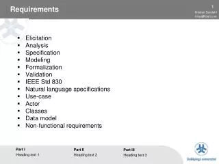
further PSL requirements • interfaces to detector control software • interfaces to DAQ system • environmental requirements: size, power, cooling • reliability to meet detector duty cycle goal • easy to maintain (change of items with lifetimes < 2years)
high power ring laser 200W GEO typring laser15W spatial filterresonator (PMC) NPRO1W frequencyreferenceresonator AOM PSL optical layout
NPRO output QR f f EOM FI BP FI modemaching YAG / Nd:YAG 3x2x6 optics QR f f BP YAG / Nd:YAG / YAG HR@1064 f 2f f 3x 7x40x7 HT@808 20 W Master High Power Slave Advanced LIGO Laser Design
PSL – stabilization scheme intensity stabilizationouter loop injection locking intensity stabilizationinner loop PMC loop frequency stabilizationinner loop frequency stabilizationouter loop
pre-stabilized -LIGO 10W laser length controll intensity controller pre-mode cleaner EO power NPRO amplifier to suspended mode cleaner temp PZT EO phase shifter reference cavity AO frequency contoller mixer
pre-modecleaner 713 MHz free spectral range linewidth: 162 kHz in s-pol. , 3.2 MHz in p-pol. circulating power 0.135MW/cm2 (for p-pol.), 2.64MW/cm2 (for s-pol.) linewidth required to filter RIN(@25MHz) of 180W laser: 3.7MHz
high power ring laser 200W GEO typring laser15W spatial filterresonator (PMC) NPRO1W frequencyreferenceresonator AOM PSL set-up
Nd:YAG Master-Laser NPRO (non-planar ring oscillator) by Innolight* • output power: 800mW • frequency noise: [ 10kHz/f ] Hz/sqrt(Hz) • power noise: 10-6 /sqrt(Hz) * US dristibution: Resonant optics Corp., San Martin CA
High Power Locking SchemeMaster • 2W Miser Mephisto 2000 Innolight • EOM: New Focus @ 29,02 MHz • Isolator: Gsänger
High Power Locking SchemeMedium Stage • 12 W med. power stage based on GEO 600 laser design opt ~ 30 % • Isolator: Gsänger high power design
12W injection-locked laser-system NPRO (non-planar ring oscillator) master laser, output power: 800mW slave laser optical components mounted on rigid resonator-spacer (Invar) 12W output power (< 5% in higher TEM modes) injection-locking stable over days
High Power Slave 87 W output power linear polarized single transverse mode M2x,y ~ 1,2
Experimental/Diode Temperature Control laser diode JENOPTIK 30 W, fiber coupled, NA 0.22; 800 m temperature resolution: 0.01K temperature fluctuations: 2-3 digits temperature stability better than 0.05K
4 boxes • each 10 X 30 W fiber-coupled diodes 1200 W pump Power Experimental/Diode Box user interface 4 systems (boxes) 40 temperatures laser diode (10) heat sink (2) 4 current controls (1 per box) ADC/DAC upcoming: • 40 diode power measurements laser power control for each diode overtemp interlocks peltier drivers
High Power Locking Scheme • 87 W high power slave single transverse mode M2 ~ 1,2 opt ~ 23 %
Results First high power injection locked laser system 87 W linear polarized, single frequency, single transverse mode ( total power of all systems ~ 101 W ) total optical efficiency 22% locking direct to 2 W master possible single frequency output power ~ 70 W
Beam Characterization Beat signals of free running slave no higher order modes detect Beam profile of locked system M2~1.1 , less elliptical beam
Relock Time relock time < 500 ms faster relock possible depending on piezo ramp
System Optimization To get full injection locked power following things has to be optimized: • Modemaching in the high power slave ( FI with compensated thermal lens ) • Outputcoupler of high power slave • optimize gain overlap of different Lasers • implement pumplight optimization
Pump Concepts mode selective pumping w = 1mm
Pump Light Homogenization 30 % more output power with homogenization better gain overlap and less distortion for low order modes
2.5 cm Pump Chamber water flow
Birefringence compensation Find working point with less birefringence
Pump Light Homogenization fluorescence w/o homogenization
Homogenization of Pump Light simulation 10 x 800 µm measured 30 x 800 µm
Pump Concepts mode selective pumping w = 2 mm
Optimization of Pump Light Distribution alignment of homogenous and centered pump light profile pump power calibration for PD-readout
Optimize Resonator • Test different laser rods 4,5 mm • Test different pump spot sizes find best laser design before doubling the system
Advanced Ligo Laser 1st. Step • Optimized laser head with respect to beam quality and output power • up to now 100 W of output power in single transverse mode are demonstrated
output QR f f BP from Master QR f f HR@1064 f 2f f HT@808 Advanced Ligo Laser 2st. Step
pump light distribution • ray tracing • analytical approximation • experimental data Finite Element Method for calculating • temperature distribution • mechanical stress • deformation heat generation gain cooling wave propagation through inhomogenous medium • finite differencing • split step fourier approach calculation of optical properties • thermal lens • stress-induced birefringence k-vector Modeling/Overview
Model assumption: cylinder symmetrical pump light distribution model takes into account temperature dependent properties wavelength dependent absorption coefficient temperature dependent heat conducitvity temperature dependent expansion coefficient temperature dependent dn/dT
initial distributed E(x,y,z0) (e. g. noise) medium free propagation mirror/aperture free propagation medium free Propagation output power beam quality mirror/aperture free Propagation no yes convergence ? Fox/Li Approach Iterative Solution of Kirchhoff integral equations • inhomogenous distributed gain, refractive index, birefringence concentrated in gain/phase sheets • propagation between gain/phase sheets and in free space described by FFT propagator
<10 nm Abberations/End Pumped vs. Transversally Pumped
Thermal Modeling/Temperature Distribution varying with pump spot diameter (pump power kept constant) 500 m