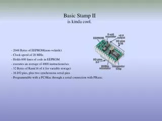
Basic Stamp Microcontroller
The BASIC Stamp microcontroller is a versatile single-board computer that utilizes the PBASIC language interpreter. It allows developers to store their code in EEPROM for both programming and data storage. With simple commands for basic I/O operations, interfacing with sensors, and connecting with integrated circuits, it enables seamless communication in networks. This guide covers programming basics, configuring ports, and implementing features like LED control and stepper motor management, while emphasizing safety precautions during circuit assembly.

Basic Stamp Microcontroller
E N D
Presentation Transcript
Basic Stamp Microcontroller 24 2 12
What is a BASIC Stamp microcontroller? • A BASIC Stamp microcontroller is a single-board computer that runs the PBASIC language interpreter in it's microcontroller. The developer's code is stored in an EEPROM, which can also be used for data storage. The PBASIC language has easy-to-use commands for basic I/O, like turning devices on or off, interfacing with sensors, etc. More advanced commands let the BASIC Stamp module interface with other integrated circuits, communicate with each other, and operate in networks.
เมื่อเข้าสู่โปรแกรมจะปรากฏหน้าจอนี้เมื่อเข้าสู่โปรแกรมจะปรากฏหน้าจอนี้
ตั้งพอร์ตการเชื่อมต่อตั้งพอร์ตการเชื่อมต่อ
เช็คความถูกต้องของโปรแกรมด้วยปุ่มนี้เช็คความถูกต้องของโปรแกรมด้วยปุ่มนี้ กด run เพื่อโหลดโปรแกรมลงหน่วยความจำของ microcontroller
เพิ่มให้มี switch สั่งให้ LED กระพริบ เพิ่มเป็นให้ LED 2 ตัวกระพริบสลับกัน
การควบคุม stepper motor หลักการทำงานของ stepper motor ดูใน sheet ประกอบ ULN 2003 ทำหน้าที่อะไร?
ลองเพิ่มจำนวน steps ลองปรับเวลา
เพิ่มให้มีการคุมด้วย switch
ข้อควรระวัง • อย่าต่อแหล่งจ่ายไฟโดยตรงเข้ากับขาพอร์ตของไมโครคอนโทรลเลอร์ (จะต้องมีตัวต้านทานด้วยเสมอ) เพื่อจำกัดกระแสที่จะไหลเข้าหรือออกจากพอร์ต มิฉะนั้น จะทำให้พอร์ตหรือตัวไมโครคอนโทรลเลอร์พังได้ • ตรวจสอบวงจรให้ถูกต้องก่อนต่อกับแหล่งจ่ายไฟ เสมอ • ระวังสายไฟที่ไม่ได้ใช้ ให้เก็บให้เป็นระเบียบโดยเสียบในช่องว่างๆ ของโปรโตบอร์ด • คอมพิวเตอร์บางเครื่องอาจมีไฟรั่วเล็กน้อย การเสียบต่อ COM PORTอย่าสัมผัสกับส่วนที่เป็นโลหะ