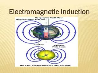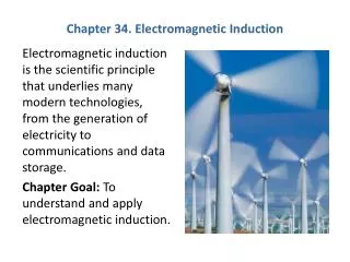
Short Version : 27. Electromagnetic Induction
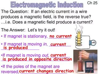
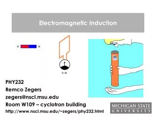
Short Version : 27. Electromagnetic Induction. 27.1. Induced Currents. 4 results from Faraday / Henry (1831). v = 0, I = 0. v > 0, I > 0. 1. Current induced in coil by moving magnet bar. v >> 0, I >> 0. v < 0, I < 0.

Short Version : 27. Electromagnetic Induction
E N D
Presentation Transcript
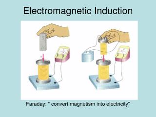
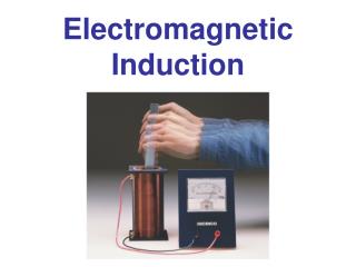
27.1. Induced Currents 4 results from Faraday / Henry (1831) v = 0, I = 0 v > 0, I > 0 1. Current induced in coil by moving magnet bar. v >> 0, I >> 0 v < 0, I < 0 2. Moving the coil instead of the magnet gives the same result.
3. An induced current also results when a current-carrying circuit replaces the magnet. 4. A current is also induced when the current in an adjacent circuit changes. changing B induces currents (electromagnetic induction)
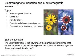
27.2. Faraday’s Law • Magnetic flux • Flux & Induced EMF
Magnetic flux Magnetic flux: Reminder: For a uniform B on a flat surface: Move magnet right more lines thru loop
Example 27.1. Solenoid A solenoid of circular cross section has radius R, consists of n turns per unit length, and carries current I. Find the magnetic flux through each turn of the solenoid. I B B out of plane
Example 27.2. Nonuniform Field A long, straight wire carries current I. A rectangular wire loop of dimensions l by w lies in a plane containing the wire, with its closest edge a distance a from the wire, and its dimension l parallel to the wire. Find the magnetic flux through the loop. Area element for integration
Flux & Induced EMF Faraday’s law of induction: The induced emf in a circuit is proportional to the rate of change of magnetic flux through any surface bounded by that circuit. C is CCW about S. Note: dB/dt can be due to • changing B caused by • relative motion between circuit & magnet, • changing current in adjacent circuit, • changing area of circuit, • changing orientation between B & circuit. C C
Example 27.3. Changing B A wire loop of radius 10 cm has resistance 2.0 . The plane of the loop is perpendicular to a uniform B that’s increasing at 0.10 T/s. Find the magnitude of the induced current in the loop. S C I CCW
Example 27.4. Changing Area Two parallel conducting rails a distance l apart are connected at one end by a resistance R. A conducting bar completes the circuit, joining the two rails electrically but free to slide along. The whole circuit is perpendicular to a uniform B, as show in figure. Find the current when the bar is pulled to the right with constant speed v. Let x = 0 be at the left end of rail. S C I CCW x
27.3. Induction & Energy m I Direction of emf is to oppose magnet’s motion. RH rule: thumb // m. Loop ~ magnet with N to left. Magnet moving right Lenz’s law : Direction of induced emf is such that B created by the induced current opposes the changes in that created the current. m I RH rule: thumb // m. Loop ~ magnet with S to left. Magnet moving left
Motional EMF & Len’s Law Motional emf: induced emf due to motion of conductor in B. Square loop of sides L & resistance R pulled with constant speed v out of uniform B. Force on e: downward force • upward I (CW) Force on current carrying wire:
< 0 S I C CW x Work done is used to heat up circuit ( E conservation ).
Application. Electric Generators World electricity generation ~ 2TW. Rotating loop changes & induces emf. Rotating slip rings. Sinusoidal AC output Work required due to Lenz’s law. Electric load Stationary brushes Rotating conducting loop Hand-cranked generator ~ 100W
Example 27.5. Designing a Generator An electric generator consists of a 100-turn circular coil 50 cm in diameter. It’s rotated at f = 60 rev/s to produce standard 60 Hz alternating current. Find B needed for a peak output voltage of 170 V, which is the actual peak in standard 120 V household wiring. Loop rotation
EM induction is basis of magnetic recording ( audio, video, computer disks, …). Iron Coil Card motion Modern hard disks: Giant magnetoresistance. Magnetic strip Information stored in magnetization pattern Swiping a credit card. Patterns of magnetization on the strip induce currents in the coil.
Eddy Currents Eddy current: current in solid conductor induced by changing . Usage: non-frictional brakes for rotating saw blades, train wheels, … Application: Metal Detectors Induced Current Nothing between coils Current detector AC Strong I Transmitter coil Receiver coil Weak I : alarm. Metal between coils
Closed & Open Circuits B of induced I points out of page Setting n // Bin C is CCW & < 0 Bin d /d t < 0 E > 0 I is CCW RH rule gives CCW I Bin C +_ B E > 0
27.4. Inductance Inductance: Mutual Inductance: Changing current in one circuit induces an emf in the other. Large inductance: two coils are wound on same iron core. Applications: Transformers, ignition coil, battery chargers, … Self-Inductance: Changing current induces emf in own circuit & opposes further changes. Applications: Inductors frequency generator / detector … [ L ] = T m2 / A = Henry
Example 27.6. Solenoid A long solenoid of cross section area A and length l has n turns per unit length. Find its self-inductance. B of solenoid:
+E direction = V along I. back emf Rapid switching of inductive devices can destroy delicate electronic devices. dI /d t < 0
Inductor (lower voltage) (lower voltage) E E + (higher voltage) + (higher voltage)
Example 27.7. Dangerous Inductor A 5.0-A current is flowing in a 2.0-H inductor. The current is then reduced steadily to zero over 1.0 ms. Find the magnitude & direction of the inductor emf during this time. + here ( E > 0 ) helps keep I flowing
Inductors in Circuits Current through inductor can’t change instantaneously. Switch just closed : I = 0, dI/dt 0; | EL | = E0 L ~ open circuit. Long after switch closing: I 0, dI/dt = 0; EL= 0; L ~ wire. Switch open: I = 0
+_ I V = IR But rate is EL< 0 ; | EL | Inductive time constant = L / R c.f. capacitive time constant = RC
Example 27.8. Firing Up a Electromagnet A large electromagnet used for lifting scrap iron has self-inductance L = 56 H. It’s connected to a constant 440-V power source; the total resistance of the circuit is 2.8 . Find the time it takes for the current to reach 75% of its final value.
Switch at B, battery’s shorted out. I exponentially. Switch at A, I. Short times: IL can’t change instantaneously. Long times: EL = 0 ; inductor wire.
Making the Connection Verify that the current in just after the switch is reopened has the value indicated Immediately after the switch is closed: L ~ open circuit. Long time after the switch is closed: Immediately after 2nd switch opening : L ~ short circuit. I in L ~ continues.
27.5. Magnetic Energy Any B contains energy. This eruption of a huge prominence from the sun’s surface releases energy stored in magnetic fields.
Magnetic Energy in an Inductor RL circuit: Power from battery Power dissipated Power taken by inductor Energy stored in inductor:
Example 27.10. MRI Disaster • Superconducting electromagnets like solenoids in MRI scanners store a lot of magnetic energy. • Loss of coolant is dangerous since current quickly decays due to resistance. • A particular MRI solenoid carries 2.4 kA and has a 0.53 H inductance. • When it loses superconductivity, its resistance goes abruptly to 31 m. Find • the stored magnetic energy, and • the rate of energy release at the instance the superconductivity is lost. In practice, Cu / Ag are incorporated into the superconducting wires to reduce R.
Magnetic Energy Density Solenoid with length l & cross-section area A : (Eg. 27.6) Magnetic Energy Density : c.f. electric energy density :
27.6. Induced Electric Fields EMF acts to separate charges: Battery: chemical reaction Motional emf: F = v B. Stationary loop in changing B : induced E Faraday’s law Induced E forms loop. Static E begins / ends on charge.
Example 27.11. Solenoid A long solenoid has circular cross section of radius R. The solenoid current is increasing, & as a result so is B in solenoid. The field strength is given by B = b t, where b is a constant. Find the induced E outside the solenoid, a distance r from the axis. Symmetry E lines are circles. Loop for Faraday’s law S CCW S out C ccw
Conservative & Nonconservative Electric Fields E For stationary charges (electrostatics) : W against E E is conservative Induced fields (electromagnetics) : E does W E is non-conservative
GOT IT? 27.7 The figure shows three resistors in series surrounding an infinitely long solenoid with a changing magnetic field; the resulting induced electric field drives a current counterclockwise, as shown. Two identical voltmeters are shown connected to the same points A and B. What does each read? Explain any apparent contradiction. Hint: this is a challenging question! VA VB = IR VA VB = 2IR
Diamagnetism Classical model of diamagnetism (not quite right) Superconductor is a perfect diamagnet (Meissner effect). B = 0: net = 0 net 0 B 0 This e slows down. This e speeds up.