Download
1 / 1
10 likes | 122 Vues
This document outlines the power supply setup for the LM96551, LM96530, and LM96570 components. It includes details on providing +5V, +3.3V, +10V, -10V, -50V, -5V, and +1.8V supplies for input and intermediate stages, with specific current consumption limits under 100mA for low voltage and 250mA for high voltage operations. Instructions are provided for ensuring the proper "ON" and "OFF" sequences and setting current limits to maximum for optimal performance. This guide is essential for efficient testing and operation of ultrasound systems.

E N D
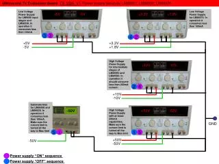
Ultrasound Tx Evaluation BoardTX_SDK_V1 Power Supply Setup for LM96551, LM96530, LM96570 +5V +3.3V +10V +50V -10V -50V -5V +1.8V Low Voltage Power Supply for LM9650 input stages and LM96530. In operation it consumes less then 100mA Low Voltage Power Supply for LM96570. In operation it consumes less then 100mA 3 3 4 2 +5V +3.3V +1.8V -5V High Voltage Power Supply for intermediate stages of LM96550 and LM96530. In operation it should consume less then 250mA current. 2 4 +10V -10V Substrate bias for LM96550 and LM96530. In operation it consumes less then 100mA. Make sure the current limit is turned all the way to Max limit -50V High Voltage Power Supply with at lease 250mA capabilities. Make sure the current limit is turned all the way to Max limit GND 5 1 1 5 +50V -50V -50V Power supply “ON” sequence Power supply “OFF” sequence