Lecture 5
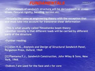
Fundamentals of sandwich structure will be derived such as stress-strain, flexural rigidity, bending, torsion etc. Virtually the same as engineering theory with the exception that one must take into account for transverse shear deformation This is what usually called Timoshenko beam theory

Lecture 5
E N D
Presentation Transcript
Fundamentals of sandwich structure will be derived such as stress-strain, flexural rigidity, bending, torsion etc. • Virtually the same as engineering theory with the exception that one must take into account for transverse shear deformation • This is what usually called Timoshenko beam theory • Another novelty is that different loads will be carried by different parts of the structure • Further reading: • [1] Allen H.G., Analysis and Design of Structural Sandwich Panel, Pergamon Press, Oxford, 1969 • [2] Plantema F.J., Sandwich Construction, John Wiley & Sons, New York, 1966 • Indices f are used for the face and c for core Lecture 5 FUNDAMENTALS
Consider beam subjected to bending moment as follows: • The strain in the fibre situated a distance z from the neutral axis: Lecture 5 FUNDAMENTALS
The applied bending moment needed to cause the curvature kx, is then (Equation 3.2); • EI: Flexural rigidity (product of elastic modulus, E, and the moment of inertia,I) • EI will be designated D for the following reason; if Young’s modulus E varies along the z-coordinate then it cannot be removed outside the integral in Equation (3.2) Lecture 5 FLEXURAL RIGIDITY
The general expression for the strain, a distance z from neutral axis will then be: Lecture 5 FUNDAMENTALS
Hence, the strain vary linearly with z over the cross section • Assuming small deflection theory, the radius of curvature can be found in terms of the displacement field by geometrical study • From Figure 3.2, it is then seen that, dx=Rdθ, and dθ=-d2w/dx2 dx Lecture 5 FUNDAMENTALS
Now the basic equations are established, one may commence calculating the cross-sectional properties and stresses in sandwich beam. • First, define the coordinate system and positive direction fro the load as in Figure 3.3: Lecture 5 FUNDAMENTALS
In order not to complicate the analysis, assume a symmetrical lay-up of the sandwich, i.e. the faces have the same thickness, tf and are of the same material with elastic modulus, Ef. The core has thickness, tc, and modulus Ec. The flexural rigidity D is then for a cross-section as in Figure 3.3 • Where d: tf + tc (the distance between the centroids of the faces) • The first term corresponds to the flexural rigidity of the faces alone bending about their individual natural axes • The second term represents the stiffness of the faces associated with bending about the centroidal axis. • The third term is the flexural rigidity of the core Lecture 5 FUNDAMENTALS
The faces are usually thin compared with the core, i.e. tf << tc, and the first of Eq ( ) is therefore quite small and is less than 1% of the second if; • As a result of materials selection, the core usually has a much lower modulus than that of the face, i.e., Ec << Ef, Hence, the third term in Eq ( ) is less than 1% of the second if • Thus, for a sandwich with thin faces, tf << tc, and a weak core, Ec << Ef, the flexural rigidity, D, can be written approximately as; Lecture 5 Approximations in the flexural rigidity
For ordinary engineering materials used in sandwich construction, the core/face thickness ratio is commonly in the regime 10 to 50 and the face/core modulus ratio between 50 and 1000 • An important fact can now be noted, the dominating term in the expression for the flexural rigidity is that of the faces bending about the natural axis of the entire sandwich • This part is the one originating from a direct tension-compression of the faces. If the adhesive joints connecting the faces to the core were absent, this term would vanish leaving only the contribution from terms 1 and 3 in Eq ( ), corresponding to the bending of two faces and one core about their individual neutral axes and hence independent of each other. Lecture 5 Flexural rigidity
This means that a major part, or almost all, of the flexural rigidity will be lost • The fact that the flexural rigidity of a sandwich consists mainly of the part originating from the interaction of the constituents is usually called the sandwich effect Lecture 5 Flexural rigidity
Using the strain definition in Equation (3.3), the stresses in the sandwich due to bending are readily found. The face and core stresses are: Lecture 5 Stresses in sandwich beam
In the same manner as outline before, a more general definition must also be found for shear stress • The maximum shear stress appears at the neutral axis, i.e., for z=0 Lecture 5 • and the shear in the face/core interface will be; Shear Stresses in sandwich beam
This means that a major part, or almost all, of the flexural rigidity will be lost • The fact that the flexural rigidity of a sandwich consists mainly of the part originating from the interaction of the constituents is usually called the sandwich effect Lecture 5 Flexural rigidity
One can now investigate the consequences of the previous findings • Consider a homogeneous plate of a material with a given Young’s modulus, E, and a given strength. • Subject a beam of this material to a bending moment • Calculate the weight, bending stiffness and strength of the beam and set them to unity • Suppose we now cut the beam in two halves and separate the parts with a core (we can do that without adding substantial weight) • Given the above analysis, one can now calculate the corresponding stiffnesses and strengths of sandwich beams and the relative properties given in Figure 3.6 will be found Lecture 5 The sandwich effect
Lecture 5 The sandwich effect
Lecture 5 The sandwich effect
![[lecture#5]](https://cdn0.slideserve.com/109460/slide1-dt.jpg)