VNR PROTOCOL FOR LABORATORIES
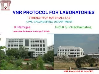
VNR PROTOCOL FOR LABORATORIES. K.Ramujee Prof.K.S.V.Radhakrishna Associate Professor, In-charge S.M.Lab. STRENGTH OF MATERIALS LAB CIVIL ENGINEERING DEPARTMENT. VNR Protocol-S.M. Lab-CED. STRENGTH OF MATERIALS LAB. VNR Protocol-S.M. Lab-CED. Topic.

VNR PROTOCOL FOR LABORATORIES
E N D
Presentation Transcript
VNR PROTOCOL FOR LABORATORIES K.Ramujee Prof.K.S.V.Radhakrishna Associate Professor, In-charge S.M.Lab STRENGTH OF MATERIALS LAB CIVIL ENGINEERING DEPARTMENT VNR Protocol-S.M. Lab-CED
STRENGTH OF MATERIALS LAB VNR Protocol-S.M. Lab-CED
Topic • Testing of materials for various important characteristics needed for design of Automobile/Machine elements. VNR Protocol-S.M.Lab-CED
1.Learning Objectives To appreciate the necessity of Hardness of material for use in Machine members. • The potential of Toughness of the material ensuring ample warning before failure of a Material. • To Recognize the importance of the Modulus of Elasticity/Rigidity of a material used in the components. • will perform tests on materials in torsion, bending,shearing,compression etc. VNR Protocol-S.M.Lab-CED
2.Bringing in the Real World Situation VNR Protocol-S.M.Lab-CED
2.Bringing in the Real World Situation VNR Protocol-S.M.Lab-CED
Bringing in the Real World Situation • The Machine/Automobile members are generally subjected to different loads like axial,Bending,Twisting,Shear and combination of these Loads. VNR Protocol-S.M.Lab-CED
Loads Compression Tension Bringing in the Real World Situation . VNR Protocol-S.M.Lab-CED
Bringing in the Real World Situation • Amember, if not designed properly, • either fails by fracturing due to excessive Stress generated (Material failure) • OR • Fails by excessive deformation • (Functional Failure) VNR Protocol-S.M.Lab-CED
Material Types can be distinguished by characteristics among the stress-strain curve. Bringing in the Real World Situation Ductile material : has ability to undergo large deformation before fracture (rupture) or breaking showing progressive fracture. Ductile materials include mild steel, aluminum and some of its alloys, copper, magnesium, lead, molybdenum,nickel, brass, bronze, nylon, teflon, and many others VNR Protocol-S.M. Lab-CED
Bringing in the Real World Situation Brittle Materials: Materials that fail in tension at relatively low values of strain are classified as brittle materials. Examples are concrete, stone, cast iron, glass, ceramic materials, and many common metallic alloys. Ordinary glass is a nearly ideal brittle material. VNR Protocol-S.M. Lab-CED
3.Fitting into the spectrum Therefore the member must be designed suitably by: 1) Choosing the appropriate material 2) Providing the required shape and size of the cross section The stiffness of the member for a given length depends on the product “AE” The selection of the material depends not only on the strength requirement but also on the suitability for the given conditions of loading and exposure. VNR Protocol-S.M.Lab-CED
Fitting into the spectrum • A) From the strength point of view , the working stress (P/A) must be less than the allowable tensile stress • Hence the material property , Allowable Stress in Tension is required for the design of a Tie. • Allowable tensile stress in the material σallow = σultimate/ η or σyield/ η where ‘η’ is the Factor of Safety ( F.O.S.) VNR Protocol-S.M.Lab-CED
Function Index Objective Tie Constraint Minimum cost Minimum weight Maximum stored energy Minimum environmental impact Beam Stiffness Strength Fatigue Geometry Shaft Index Column Fitting into the spectrum Mats. Selection: Multiple Constraints Mechanical Thermal Electrical….. VNR Protocol-S.M.Lab-CED
Fitting into the spectrum TORSION The highest shear stress, for a given torque T, experienced by a shaft is given by: BENDING The highest stress, for a given bending moment M, experienced by a beam is at the surface a distance y furthest from the neutral axis: The beam fails when the torque is large enough for to reach the failure shear stress of the material: The beam fails when the bending moment is large enough for σto reach the failure stress of the material: VNR Protocol-S.M.Lab-CED
The object function is Constraint 1: Stiffness where so, If the beam is to meet both constraints then, for a given material, its weight is determined by the larger of m1 or m2 Constraint 2: Strength where so, Choose a material that minimizes or more generally, for i constraints Multiple Constraints: A Simple Analysis A LIGHT, STIFF, STRONG BEAM
4.Keywords in Experiment • Design • Machine Element • Axial tensile force • Bending • Twisting force • Hardness • Compression • Impact • Ultimate Strength • Modulus of Rigidity • Stiffness VNR Protocol-S.M.Lab-CED
5.Linking keywords with concepts For resistance against failure • Ultimate shear strength • Impact Energy • Hardness • Torsional Rigidity • Flexural Rigidity • Limitations on Shape and size of Cross section VNR Protocol-S.M.Lab-CED
Linking keywords with concepts For requirement of limited max extension • Modulus of Elasticity (E) • Moment of Inertia (I) • Beam with supports • Flexural rigidity (EI) • Stiffness of the member (AE/L),(kEI/L) • Extension • Measuring deflection -Dial gauge with magnetic base. VNR Protocol-S.M.Lab-CED
6.Generation of Exercises • To Design a Machine member subjected to the given actions of Shear,Twist and Impact Loads against failure. • Designing of a Machine member against failure due to Hardness. VNR Protocol-S.M.Lab-CED
7.Focusing on one Exercise or Problem • For facilitating the design, - a direct Shear Test for determining allowable Shear strength, • Hardness Test for determining Indentation hardness of a Metal, • Torsion test for determining the Rigidity Modulus of a Material , • Impact Test for a notched specimen to determine the toughness property. VNR Protocol-S.M.Lab-CED
8.Design of Experiments to solve the problem • To decide which of the Tests are to be conducted on what machines using appropriate apparatus or accessories, and loading conditions. VNR Protocol-S.M.Lab-CED
9.Verification To compare the results obtained with standard values Ultimate strength and yield stress are to be Compared with codal provisions. VNR Protocol-S.M.Lab-CED
10.Setup • Support system Hardness tests • Torsion test set up. . • Impact test set up • Shear test • Compression test • Spring test set up. VNR Protocol-S.M.Lab-CED
11.Confirmation • Finalizing the suitability of the material for the given conditions and deciding the shape and size of the member. VNR Protocol-S.M.Lab-CED
12. Experiment -- Direct Shear Test for determining allowable Shear strength • Hardness Tests for determining Indentation hardness of a Metal, • Torsion test for determining the Rigidity Modulus of a Material • Impact Test for a notched specimen to determine the toughness property. • To conduct Spring test for determination of Modulus of Rigidity. • TO conduct compression test to know the Ultimate strength in compression. VNR Protocol-S.M.Lab-CED
14.Conclude • After getting the allowable stresses in bending,Twisting and shearing and Material Properties like Modulus of elasticity (E) and Modulus of Rigidity(C) and other Mechanical properties like Hardness and Toughness , the member can be designed for determining the area of cross section (A) VNR Protocol-S.M.Lab-CED
Conclude Design: • To select suitable member( based on material Property) and size and shape to satisfy strenngth requirements. • The limitations on the shape and size of the member to fit into the machine are to be taken into consideration while finalizing the design. However, a different material may be chosen , if required, to satisfy the conditions of limitations on area and shape. VNR Protocol-S.M.Lab-CED
LAB. REPORT • 3 persons per 1 group • Analyze results together • Each person of the group will write their own Discussion and Conclusion. • 1 group per 1 report with multiple discussion and conclusion.
LABORATORY SAFETY RULES • Keep yourself and others safe –Be aware of your own and others’ safety • Know emergency procedures (fire escape routes) • Report any perceived safety hazards • No working alone • No eating or drinking in the lab • Wear appropriate safety equipment • No loose clothes and long hair around machines • Do not work with electrical appliances in the presence of water • Do not put obstructions in walkways –keep fire escape routes completely clear • Clean up any spills immediately • Know the hazards of any materials or machines with which you are working VNR Protocol-S.M.Lab-CED