CHAPTER 5 FLEXIBLE PAVEMENT DESIGN
CHAPTER 5 FLEXIBLE PAVEMENT DESIGN. Stresses and Strains in flexible Pavements. • The material properties of each layer are homogeneous • Each layer has a finite thickness except for the lower layer, and all are infinite in lateral directions.

CHAPTER 5 FLEXIBLE PAVEMENT DESIGN
E N D
Presentation Transcript
• The material properties of each layer are homogeneous • Each layer has a finite thickness except for the lower layer, and all are infinite in lateral directions. • Each layer is isotropic, that is, the property at a specific point such as Ai is the same in every direction or orientation. • Full friction is developed between layers at each interface. • Surface shearing forces are not present at the surface. • The stress solutions are characterized by two material properties for each layer, i.e., (μ, E). Assumptions in Multi LayeredElastic Systems
At any point, 9 stresses exist. They are 3 normal stresses (sz, sr, st) and 6 shearing stresses ( trz =tzr; tr t = ttr; ttz =tzt) • At each point in the system there exists a certain orientation of the element such that the shearing stresses acting on each face are zero. – The normal stresses under this condition are principal stresses and are denoted by s1(major), s2 (intermediate) and s3 (minor). Stresses in Layered Systems
Boussinseq assumptions: 1.soil is ideal mass; 2.soil are homogenous; 3.possion`s ratio is constant in all directions, and E is constant; 4.soil is isotropic , that mean x = ONE – LAYER SYSTEMS
Pavement stresses , strains and deflections are caused by: 1.traffic loading, 2.daily or seasonal temperature and moisture changes; 3.changes in the conditions of pavement support. Determination of stresses and deflections in multi-layer-system:
The general assumptions of the multi-layer theory are: 1.Materials used in each layer is homogenous; 2.Finite thickness of layer; 3.Infinite lateral dimensions; 4. Isotropic properties; 5. Full friction at layer interfaces; 6 .Shear forces at surface =0; 7 .Each layer’s material is characterized by Poisson’s ratio (u) and elastic modules (E).
Equivalent single wheel load (ESWL) ESWL defined as the load on a single tire that will cause an equal magnitude of pre-selected parameter (stress, strain, def.), to that resulting from a multiple wheel load at the same location from the pavement. There are two methods for determination the ESWL , based on equal stress and equal deflection.
Solution (1) For dual system a = (Q/ p)0.5 = (9000/3.14 x90)0.5 = 5.64 in. Max. stress at point (a) = 1 + 2 Load (1): z/a = 30/5.64 =5.32, r/a =0.0 From z influence curve (Fig.58) stress ratio = 5.1/ 90 1 =Pt x stress ratio = 90 x(5.1/90) =5.1 psi.
load (2): z/a = 5.32, r/a =5.32 2 = pt x stress ratio = 90x(0.95/90) =0.95 psi. Total = 5.1 + 0.95 = 6.05 psi b) For ESWL max. = Pt x stress ratio = 6.05 stress ratio = 6.05 / Pt = 6.05 / 90 = 0.067 By using the chart: r/a = 0.0 , stress ratio = 0.067 x 90 = 6.05 z/a = 5 = 30 / a a = 6.0 in. PE = .Pt. a2 = 3.14x 90x 6x6 = 10.174 Ib.
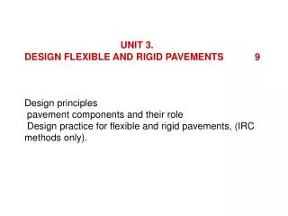
The design methods are classified to three main groups as follows: 1. Theoretical methods; 2. Empirical methods; 3. Empirical-theoretical methods.
These methods can be classified into three groups: 1-Methods based on soil classification tests , as example group index method. 2-Methods based on soil strength tests as CBR-, asphalt institute-and national crushed stone association method. 3-Methods based on the results of road tests as AASHO and road test method. 2. Empirical Methods:
Fig.69 shows an approximation of desirable total permanent th. based on truck traffic volume and the group index of the subgrade. This method is simple, but has many limitations and it could be lead to an over -or under designed pavement. 2.1.The Group Index Method:
Modified CBR method or asphalt institute method is shown in Fig.71. By using this method , pavement thickness depends upon traffic classification . Tab.27 shows the determination of each class . The relation between traffic classification and wearing surface thickness is in Tab.28. 2.2. CBR Method: