SiD Machine Detector Interface (MDI)
This presentation covers the ongoing activities related to the Machine Detector Interface (MDI) for the SiD (Silicon Detector) collaboration, outlining critical aspects such as backgrounds and detector design, primary particle interactions, and the implications of accelerator design. Key discussions focus on particle and radiation effects, detector components design, engineering challenges, and alignment systems for optimizing luminosity. Collaboration with multidisciplinary teams is emphasized, alongside the essential updates needed for site-specific designs as the ILC project progresses.

SiD Machine Detector Interface (MDI)
E N D
Presentation Transcript
SiD Machine Detector Interface (MDI) Tom Markiewicz/SLAC U. Tokyo, Japan 3 September 2014
MDI Activities (I) • Backgrounds and Detector Design • Primary particles produced in the beam-beam interaction • Disrupted e- or e+ beam (off energy, off angle), beamstrahlung photons, e+e- pairs, hadrons neutrons • Muons from beam halo scraping in the collimation system • Synchrotron radiation (SR) photons, especially from the final doublet • Secondary particles in detector after primary particles strike something • e+e- pairs striking BeamCal cause backgrounds in VXD, Tracker and Calorimeters • Neutrons streaming back from beam dumps • Accelerator Design • Work closely with the BDS “Beam Delivery System” group • Collimation system, Final Focus, Extraction Line • Work with the LEP“Luminosity, Energy & Polarization” group • Work with those selecting IP spot parameters • Detector Design • Beampipe and BeamCal in particular • Detector resident masks, apertures T. Markiewicz/SLAC
MDI Activities (II) • Engineering • Work with the magnet designers: QD0 and QF1 especially • Work with mechanical engineers: • Location, support & alignment of everything within r<30cm • Push-pull mechanical and cryogenic systems • Work with civil engineers: underground IR Hall, above ground Assembly Hall • Multidisciplinary: • Radiation protection: self-shielding, “PACMAN” design, etc. • Shielding design and radiation calculations • Vibration measurement & control, especially of QD0 • Alignment, especially of QD0 • Metrology • Frequency Scanning Interferometer to re-establish alignment after a push-pull • Cryo: • guaranteeing system, lines, interconnects consistent with detector design and push-pull operation • Vacuum for z<200m • Feedback to stabilize/maximize Luminosity: “FONT” BPM and Kicker • Beam commissioning with or without detectors T. Markiewicz/SLAC
MDI People • The Future • Everything that has been done to produce the LOI/DBD will need to be re-done in the context of the Japanese site specific design • Many results used for the design are >6 years old • Details have changed yet not been incorporated into a self-consistent collection of results • Design changes: new L* desired by AD&I team • “Value Engineering” should be applied as ILC project comes on the mass shell • A new team must learn how to use existing tools or develop better tools • Many projects have not begun or have been abandoned for lack of available personnel • Pastcontributors (partial list): • Takashi Maruyama & Lew Keller (backgrounds) • Mike Woods, Mike Hildreth(NDU), Eric Torrence (UO), Ken Moffeit (LEP Issues) • Mario Santana (FLUKA radiations calcs) • Wes Craddock (Solenoid & Yoke design; Cryo) • Marty Breidenbach, Phil Burrows(OU), Marco Oriunno, TWM (all) • Brett Parker, Andy Marone & Bill Sporre (BNL QD0) • Bill Cooper(FNAL), Mike Sullivan, Sasha Novokhatski (Beam Pipe, Vacuum, HOM Heating) T. Markiewicz/SLAC
SiD Schematic(before Support Tube adopted) Beampipe Spider Support QF1 L*=9.5m LumiCal QD0 L*=3.5m FB Kicker W Mask Beampipe Bellows & Flange FB BPM QD0 Service Pipe BeamCal PolyCarbonate QF1 Cryostat QD0 Cryostat ECAL HCAL Door Yoke PACMAN T. Markiewicz/SLAC
SiD Schematic(Door Closed) Beampipe Spider Support Movers QF1 L*=9.5m LumiCal QD0 L*=3.5m FB Kicker W Mask Beampipe Bellows & Flange FB BPM QD0 Service Pipe BeamCal PolyCarbonate QF1 Cryostat QD0 Cryostat ECAL HCAL Door Yoke PACMAN T. Markiewicz/SLAC
SiD Schematic(Door Open 2.8m) Beampipe Spider Support Movers QF1 L*=9.5m LumiCal QD0 L*=3.5m FB Kicker W Mask Beampipe Bellows & Flange FB BPM QD0 Service Pipe BeamCal PolyCarbonate QF1 Cryostat QD0 Cryostat ECAL HCAL Door Yoke T. Markiewicz/SLAC
SiD Schematic(Door Open 2.8m) PACMAN QF1 L*=9.5m Barrel Yoke QD0 L*=3.5m Solenoid Cryostat FB Kicker HCAL HCAL Door Yoke Cryo Chiller QD0 Service Cryostat T. Markiewicz/SLAC
MDI Projects 2011-12 for DBD: • Add real vacuum components to beamline to make sure it is buildable • QD0 Support Tube and Magnet Mover System • Frequency Scanning Interferometer System • Vacuum and HOMs Older: • Self Shielding Calculations (2010?) • PACMAN Engineering (2008?) • Beam-Beam Backgrounds, DID/antiDID, Apertures (2006 and for “SB2009”) T. Markiewicz/SLAC
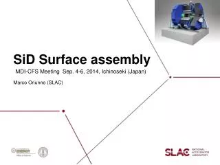
Granada LCWS’11 Engineering ModelGo from PPT Engineering to COTS parts G. Anzalone/SLAC T. Markiewicz/SLAC
More Aggressive Bellows Design Assume functionality of double multi-convolution bellows provided by bellows outboard of the VXD support Need to ensure adequate clearance between beampipe and all FCAL components Rejected Conservative Design 2-multi & 1-single convolution bellows to allow FCAL position & VXD angle adjust Suggested that this bellows “comes for free” if back end of cone appropriately engineered Handshake with QD0/FCAL Support Scheme Essential 22% Evts in LumiCal lost T. Markiewicz/SLAC
Vacuum: Still Assumes QD0 Cryo-Pump Only,But….. Recent suggestion to eliminate individual beampipes within BeamCal and the Low-Z absorber for better conductance Previous Version Implication to reduced BeamCal acceptance not yet considered (“Virtual”?) Single Convolution Bellow in front of BeamCAL T. Markiewicz/SLAC
Space Behind BeamCal Increased from 100mm→277mm to accommodate BPM W-Mask to protect QD0 from Pairs Common or Individual bellows 4-electrode 100mm stripline1um resolution BPM Increased separation to accommodate bellows, BPM and flanges T. Markiewicz/SLAC
Transverse Space Behind BeamCal Tightly Constrained • Electro-mechanical Design of BMP & Kicker by S. Smith/SLAC T. Markiewicz/SLAC
Evolution of QD0-QF1 region • Valve/Pump Out/RGA assemblies near QF1 end • QD0 Service Line to 2K chiller extended maximally to rear • Support tube behind QD0 extends to allow 2.8m door opening transitioning to a half-cylinder for access Front QD0 9236mm Front QD0 3283mm Door plates Door Ring 5683mm QD0 Service Line Back end of QD0 6933mm Wedge Alignment System in Pockets in Door Ring Back end of Support Tube FB BPM 550mm FB Kicker8090mm from IP G. Anzalone/SLAC Valve Assembly T. Markiewicz/SLAC
Plan & Elevation Views of Disconnect & Pumpout Valves 1-1/2” Gate Valves Angle Valve for Roughout Pump Formed Bellows & Disconnect Flanges Ion Pumps All Vacuum Parts from MDC Catalog G. Anzalone/SLAC T. Markiewicz/SLAC
Elevation View at 2.8m Door Opening Kicker with Electrodes Alignment Wedge Support tube cut to semi-cylinder at rear Semicircular plate and strut at end of support tube G. Anzalone/SLAC T. Markiewicz/SLAC
QD0 Cutaway Andy Marone/BNL T. Markiewicz/SLAC
200mm 2250mm 760mm diameter Overall service cryostat dimensions Detailed Cryo-engineering Based on Similar Magnets Built for HERA Local “Service Cryostat” Back End of QD0 B. Parker et al, BNL T. Markiewicz/SLAC
Integration of the QD0 cryoline He2 cryoline QD0 service cryostat Ancillary platform Hilman Rollers T. Markiewicz/SLAC
BNL Design of QD0 Support and Alignment System • ANSYS analysis of QD0 outer can in either original 0.25” or suggested 1” thickness shows unacceptable deformation of cold mass support structure • BNL designed an external support tube and a compact mover system Bolt Hole Rotation Pt. Bill Sporre/BNL T. Markiewicz/SLAC
Support Tube/QD0 Radial Clearances R216mm Hole in Ø620mm Fe Cylinder at center of Endcap Doors R216.00 * 6.00 R211.00 Cryostat Thickness = ¼” QD0 OD reduced from 390mm (4.5m L* design) by 2 x 0.007 x 1m = 14mm Tracker inner radius NEEDS TO BE increased from 200mm 216mm so it can slide over support tube to allow access to VXD
LOI Concept: FCAL supported by clam-shell bolted to QD0 Cryostat Marco Oriunno/SLAC T. Markiewicz/SLAC
Support Tube Analysis Weight Distribution When LumiCal & BeamCal Supported on Extension of QD0 Cryostat Support Tube 980 kg QD0 908 kg M. Oriunno/SLAC
Displacements (mm) VM Stresses (Kgf/mm2) M. Oriunno/SLAC Door Closed: 100um deflection Supports
Displacements (mm) VM Stresses (Kgf/mm2) M. Oriunno/SLAC Door Open 2m: 2.2mm deflection 2 m VXD Supports Tracker
Displacements (mm) VM Stresses (Kgf/mm2) M. Oriunno/SLAC Door Open 2.8m: 6mm deflection 2.8 m VXD Tracker Supports
Support Tube I.D. Ø390 mm O.D. Ø470.8 mm 50 mm QD0 Ø390 mm 1490 mm Support Tube I.D. Ø420 mm O.D. Ø470.8 mm Bill Sporre/BNL Support Tube I.D. Ø420 mm O.D. Ø470.8 mm Bolt Hole Rotation Pt. 1374 mm T. Markiewicz/SLAC
Support Tube Analysis SetupDoor Open 2m Rear Support Point Bill Sporre/BNL Rear Support Point Wedge Support Points 3.6mm 5.7mm Wedge Support Points
QD0 Wedge Design Concept Total Pad Travel as is = .475in Height of pad and distance of displacement will be changed pending analysis on sagging of beam line. Conceptual design only at this point Motor & Drive Rod system not yet done Limit Switches Potentiometer Pads located in cutouts in iron ring to which door plates are welded 216<r<620mm Bill Sporre/BNL
QD0 Wedge Design Concept Bill Sporre/BNL
Frequency Scanning Interferometry • Pioneered by Armin Reichold et al at Oxford for ATLAS • Oxford has commercialized a system bought by LCLS to monitor adjustable gap undulator: many heads • In SiD context, R&D program by Keith Riles et al at U. Michigan 2003-2007 (for SiD tracker) & 2011-2012 (for QD0) • Established an 8-channel optical table in Michigan lab • Verified 1-D, 2-D displacement measurements with sub-micron precision • Available equipment limits 3-D displacement test to few-micron precision, but should be fine • Developing corner cubes and customized beam launchers • Currently compact and light enough for MDI application, but not for SiD tracker T. Markiewicz/SLAC
FSI Grid for Monitoring QD0 QD0 QF1 Keith Riles, Hai-Jun Yang/U. Michigan T. Markiewicz/SLAC
IP Vacuum M. Sullivan/SLAC • VACCALC: “ A Method for Calculating Pressure Profiles in Vacuum Pipes”, SLAC-PEP-II-APNOTE-6-94 • The outgassing rate is taken to be 0.1 nTorr•l/s/cm2. If cryo-pump only 136 nTorr • If add 10 l/s pump 69 nTorr • If add 20 l/s pump 46 nTorr T. Markiewicz/SLAC
Vacuum Between QD0 and QF1No Problem! Assume the cryostat beam pipes have a total pumping of 500 l/s per cryostat One 100 l/s ion pump for each pipe between the cryostats as drawn Incoming Beam Pipe Outgoing Beam Pipe M. Sullivan/SLAC T. Markiewicz/SLAC
Vacuum Upstream of FF QuadsNeeds a Design! Assume a 50 l/s ion pump every 2 m 20mm diameter beampipe <p> ~ 23 nTorr Add distributed pumping Antechamber, pumpscreen, NEG, … And/or: Larger diameter beampipes, heater tapes to lower outgassing rates, etc. M. Sullivan/SLAC T. Markiewicz/SLAC
Beam-Beampipe Interactionat the IP and in QD0 Beam-induced wakefields result in power loss due to trapped higher order modes and resistive wall heating These have been calculated by A. Novokhatski for the current IR geometry using MAFIA and NOVO codes: See: http://ilcagenda.linearcollider.org/materialDisplay.py?contribId=2&materialId=slides&confId=5596 Effects are very dependent on exact geometries, materials, shielding schemes and contact resistance Sasha Novokhatski/SLAC Wakefields and Bunch field as beam passes BEAMCAL and LUMICAL T. Markiewicz/SLAC
Summary of HOM Heating at IP • Average power of the wake fields excited in IR is around 30 W for nominal parameters (6 kW pulsed) • 90% from modes excited in pipe (geometry (R/Q) & frequency dependent) • 10% from resistive wall heating • In the QD0 region there is an additional ~4W from resistive losses in the pipes and wakefields, excited by pipe diameter changes, due to the shielded bellows • Flange edge size, contact resistance, coatings important • Heating from BPMs and kickers must be added Full 3D LOI Beam Pipe (no bellows, flanges, or pump ports included) T. Markiewicz/SLAC Sasha Novokhatski/SLAC
Self-Shielding and PACMAN • PACMAN shields IR Area between the detector and the beam tunnel • Current Concept has a SiD-mounted piece and a ILC/SiD common piece to accommodate different detector sizes and QD0 support schemes • Figures of merit are “Total Dose” and “Dose Rate” • Relevant Japanese authorities need to be educated about the nature of ILC pulsed beams • Dose Rate limits (which seem artificially low given the short time scale of an “accident” (1ms)”) need to be re-evaluated • Handling of PACMAN sub-pieces will likely determine underground crane requirements • Design of UG IR Hall, tunnel lip that holds QF1, interface with platform motion system, QD0 support and push-pull all argue for active work in this area T. Markiewicz/SLAC
Current SiD “PacMan” Rotating Hinged Design Electrical motor, low friction hinges M. Oriunno, SLAC T. Markiewicz/SLAC
SiD elevation at beam plane Large PACMAN Geometry: pacman and SiD B-B’ SiD elevation at beam plane Small PACMAN SiD elevation at beam plane Large PACMAN 120 cm steel + 250 cm concrete 50 cm steel + 170 cm concrete T. Markiewicz/SLAC M. Santana, SLAC, LCWS 2010
20 R.L. Cu target in IP-9 m. Small pacman. 9 MW 9 MW 9 MW 9 MW • 1000 µSv/event • 18000 mSv/h BEAM PLANE PENETRATION PLANE µSv/event MSL - SLAC T. Markiewicz/SLAC 42 M. Santana, SLAC - 2010 LCWS Beijing
20 R.L. Cu target in IP @ 9 m. Large pacman. 9 MW 9 MW 9 MW 9 MW BEAM PLANE PENETRATION PLANE • 10 µSv/event • 180 mSv/h µSv/event M. Santana, SLAC - 2010 LCWS Beijing MSL - SLAC T. Markiewicz/SLAC 43
Provisional conclusions • Small pacman and pacman-cavern interface are sufficient in terms of dose per event. • Beam aborted after 1 Train • However, the dose rates for the small pacman are very high: • Proven mechanisms should be installed to: • avoid these accidents to occur • shut off beam after 1 train (200 mS) • Possible Debates • The large pacman complies with all criteria. • The penetrations in the pacman don’t require local shielding. • The shielding of the detector may be insufficient to comply with dose rate limit. Exclusion area? • More studies ongoing (mis-steering…) T. Markiewicz/SLAC M. Santana, SLAC
Backgrounds & Forward Calorimetry • All studies done by T. Maruyama in GEANT3 (pairs, SR) and FLUKA (Neutrons from Dump, Dose Rates) • Last looked at for “SB 2009” IP Parameters and presented early 2011 • Have not kept up with changes to nominal beam parameters, beam energy variations, or changes to FCAL • Questions of DID/anti-DID implementation, “bent solenoid”, new L*, beampipe variants, etc. should be investigated T. Markiewicz/SLAC
SiD Forward Region LumiCal 20 layers of 2.5 mm W + 10 layers of 5.0 mm W BeamCal 50 layers of 2.5 mm W ECAL Beampipe +/- 94 mrad (detector) +101 mrad, -87mrad (ext. line) 3cm-thick Tungsten Mask 13cm-thick BoratedPoly Centered on the outgoing beam line T. Maruyama SLAC T. Markiewicz/SLAC
Pair edge and Beam pipe design • Pairs develop a sharp edge and the beam pipe must be placed outside the edge. • Find an analytical function of the edge in Pt vs. Pz space. • Taking into account the crossing angle and solenoid field, draw helices in R vs. Z space. SB2009 500 GeV TF Pt=0.032 Pz0.43 Pt (GeV/c) Pz (GeV/c) T. Maruyama SLAC T. Markiewicz/SLAC
SiD beam pipe and pairs edgeMessage: Aggressive Beampipe 500 GeV RDR Low P 500 GeV RDR Nominal T. Maruyama SLAC T. Markiewicz/SLAC
Detector-Integrated-Dipole • Total pair energy into BeamCal is half. • 10 TeV/BX vs. 20 TeV/BX with NO-DID. • Pair distribution is symmetric and more confined. • No. photons backscattering to the tracker is half. SiD Solenoid We want Anti-DID. DID T. Maruyama SLAC T. Markiewicz/SLAC
VXD hit density / train 100 hits/mm2 • Detector tolerance • Use generic 1% pixel occupancy • Dependent on sensor technology and readout sensitive window. • Standard CCD 20m x 20m • 2500 pixels/mm2 • 6 hits/mm2/sw(assuming 1 hit 4 pixels) • Fine pixel CCD 5m x 5m • 40000 pixels/mm2 • 100 hits/mm2/sw(assuming 1 hit 4 pixels) 6 hits/mm2 T. Maruyama SLAC T. Markiewicz/SLAC