Download

1 / 40
400 likes | 578 Vues
ASI-SRV General purpose modules for the pre-processing of remote sensed optical data. Massimo Musacchio, Sergio Teggi, Fabrizia Buongiorno, Angelo Amodio, Marco Gregnanin, Giulia De Marzi, Stefano Vignoli, Sergio Perelli, Vincenzo Santacesaria.

E N D
ASI-SRV General purpose modules for the pre-processing of remote sensed optical data Massimo Musacchio, Sergio Teggi, Fabrizia Buongiorno, Angelo Amodio, Marco Gregnanin, Giulia De Marzi, Stefano Vignoli, Sergio Perelli, Vincenzo Santacesaria
The ASI-SRV provides support to the following volcanic activity phases addressed by the Italian Civil Protection Department (DPC): • Surveillance and early warning • Sin-eruption phase • Post-eruption phase
Howdoes ASI-SRV works EO-non EO data Providers Added value Products
ASI-SRV system will be developed in 3 phases • In the first version the core of the system has been realized, including modules/algorithm well known and consolidated (TES, VAOT, Water Vapour, Effusion Rate, SO2 and LAOT) READY TO BE OPERATIVE • During the following phases RTD based module will be developed and implemented (VAMP, Surface change detection, CO2 , Multiparametric analysis )
To optimize the computer processing time the ASI-SRV architecture is based on two data processing chains in order to get advantage of partnership infrastructures and laboratories This presentation is aimed to the “Optical-based” modules . The Optical data processing chain is localized in Rome at INGV The SAR data processing chain is localized in Naples at CNR-IREA
Several spaceborne based EO optical data will be acquired and processed: • NASA EO-1 Hyperion • NASA Terra/Aqua MODIS • NASA Terra ASTER • NOAA AVHRR • EROS • SPOT • Quickbird • Each data is furnished with specific spectral and spatial characteristics
Pre crisis Surface Thermal anomalies monitoring ASTER VAOT Volcanic Aerosol Optical Thickness estimation Hyperion Water vapour estimation Hyperion Crisis Effusion rate AVHRR, MODIS Ash clouds optical characteristics (VAMP) AVHRR, MODIS Low resolution Aerosol Optical Thickness (LAOT) AVHRR MODIS Degassing plumes SO2 Characterization AVHRR MODIS Post Crisis Change detection on surface characteristics due: Lava flow Hyperion and HI-RES Ash cover Hyperion and HI-RES
Lower Revisit Time Higher Spatial Resolution Less than 1 mt About 1 km
Level 1 Coreg Atmospheric Correction Calibration L1A Auxiliari L1B L1C L1D Sensor Radiance Sensor Reflectance BoA Radiance BoA Reflectance Sensor Radiance Sensor Reflectance Correction terms Digital Count Lup Ld ..... DEM Shaded Slope Aspect Apparent Radiance Apparent Reflectance DEM Shaded Slope Aspect Level 2 Vector generation L2A L2B L2D L2C Generic Processor Map Classified Mask Map Vectorial Layer Classified Mask sensor Geometry DEM Geometry DEM Geometry DEM Geometry Level 3 L3B L3A Time, spatial Processor DEM Geometry sensor Geometry
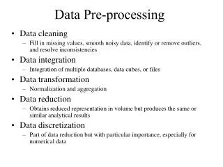
Generalpurposesmodules Tohave EO “standardized” data, readytobeprocessed, bymeansof • Radiometriccalibration, • Resizedwith a definedgeographicextension and coverage, • Atmospheric and topographiceffectremoved
GIS ReferencingTool The need to have common activities performed on the SRV product led to the development of a set of common tools, in order to perform, on different image standards, the same operations. The common tools (named GTR) are devoted to: • cut and mosaic of the input images • coregistration of input DEM and georeferencingof final SRV products
Within the ASI-SRV project a well defined geographic window has been defined for each of the three area of interest. (Vesuvio Campi Flegrei, Etna). This requirement leads to cut the low-res images, since they span over a geographic area wider than the one of interest; while each hi-res image may cover an area which is more narrow than the desired window, so a mosaic of several images followed by a cut of the temporary image obtained is needed. The tasks are made more complex by the fact that input images are provided in sensor geometry, so the cut has to be done in an appropriate way, in order to avoid the loss of points falling into the desired geographic window.
The DEM Co-registration tool implements the two major functions of orthorectification and georeferentiation of raw images. • The following two different models will be used: • Satellite Sensor Rigorous Orbital Model • Rational Polynomial Coefficients (RPC) • Dem coregistration module produces HDF file as output. This output will be used as input for all DPS. The output level of the generated product is 1C (e.g. ASTER_1C, AVHRR_1C) The tools are automated and do not require human interaction. The tools execution is scheduled by the SRV system.
No specific algorithms are required. The module consists in the mere application of calibration coefficients. • The ASTER and HYPERION data will be calibrated, while MODIS data will be not calibrated because level 1B data products contain calibrated radiances for all 36 MODIS bands and reflectances for the reflective Solar bands (Bands 1 through 19 and 26).
Radiometric Calibration Module • ASTER • Input: Level 1B in Digital Number (DN) • Algorithm: Rad=(DN-1)*ASTERFACT (ASTERFACT are ancillary data files) • Output: Radiance [W/m2/ster/m] • HYPERION • Input: Level 1R in Digital Number (DN) • Algorithm: Rad=(DN)* 1/40 (VNIR ) Rad = (DN)*1/80 (SWIR) • Output: Radiance [W/m2/ster/m]
Using CIRILLO the spectral values of atmospheric terms, (i.e. transmittances, reflectance contribution due to solar radiance scattered by the atmosphere and downward spherical albedo of the atmosphere) are computed The second reason to prefer CIRILLO is due to the capability to evaluate altitude and b factor for each pixel of the image. For these calculations CIRILLO requires as input three images (files), geographically registered with the image to be corrected and with the same spatial resolution, containing elevation, slope and aspect
The sun radiance that reaches directly the pixel viewed by the sensor (target) and that is directly reflected by the target to the sensor; • The sun radiance that reaches directly the pixel viewed by the sensor (target) and that is reflected by the target to the sensor following a multiple scattering path; • The sun radiance that reaches the target following a multiple scattering path and that is directly reflected by the target to the sensor; • The sun radiance that reaches the target following a multiple scattering path and that is reflected by the target to the sensor following a multiple scattering path; • The sun radiance that directly reaches the surface surrounding the target and that is reflected by the surface to the sensor following a multiple scattering path; • The sun radiance that reaches the surface surrounding the target following a multiple scattering path and that is reflected by the surface to the sensor following a multiple scattering path; • The sun radiance that is directly scattered by the atmosphere to the sensor without reaching the ground. G A-B-C-D-E-F All of these terms, with the exception of G), are also influenced by the orientation of the surface with respect to the sun illumination direction.
ASI-SRV OPTICAL SENSOR DATA PROCESSING MODULES Massimo Musacchio, Malvina Silvestri, Claudia Spinetti, Stefano Corradini, Valerio Lombardo, Luca Merucci, Maria Fabrizia Buongiorno, Sergio Pugnaghi, Gabriele Gangale, Lorenzo Guerrieri, Sergio Teggi, Vincenzo Santacesaria, Sergio Perelli
For each product a historical series of remote sensed data have been processed By means of specific algorithm and using Auxiliary and Ancillary… …the product is obtained Shapefile Before to post on the foreseen WEBGIS each raster needs to be converted in a ESRI like shapefile
Objective of the GTA is the generation of a synopticview of a huge volume of heterogeneous data • Discontinuous measurements • Webcam network • UV-scanner network for SO2 flux • Seismic network • GPS permanent network • Gravimetric network • Magnetic network • Analysis of the erupted ash • Analysis of the erupted products • Geologic and structural surveys • Thermal mapping from helicopter • Lava mapping from field
At the end of the scientific processing chain, raster classified products are available, and they need to be georeferenced before their transformation in vector products, in order to be displayed as a geographic information layer on a map. This task is performed by the “Map Projection” module, in order to warp them in an UTM projection. This georeferenced product is then stored in a Geo-TIFF file, that contains all the information needed for a correct visualization on a GIS. The product obtained is then ready to be analyzed by the Operator using the GTA, in order to validate or discard it before the publishing to the end user.
The GTA is a customization of ESRI ArcGIS Desktop to support the operator in performing the Validation Process Workflow. GTA will use ESRI ArcGIS (and its extensions): ArcGIS is powerful to manage a huge amounts of SRV products ArcGIS is widely used within DPC and INGV ArcGIS includes a wide variety of programmable components, so that plug-in functionalities to validate SRV products can be integrated ArcGIS, using some extensions, is compliant with the OGS protocols to be used in the frame of the project (LDS)
For further information on ASI-SRV project contact: Maria Fabrizia Buongiorno: buongiorno@ingv.it