Understanding MOSFET Cut-off and Saturation Regions in NMOS and PMOS Devices
This document covers the piecewise models for NMOS and PMOS transistors, focusing on the cut-off, triode, and saturation/pinch-off regions. It details the conditions under which each region operates, including the influence of gate-source voltage (VGS) and drain-source voltage (VDS) on the drain current (ID) for both NMOS and PMOS devices. Key equations for drain current in different regions are provided, along with a discussion on conduction parameters and how doping concentration affects threshold voltages. Additionally, it raises questions about design considerations in FET applications.


Understanding MOSFET Cut-off and Saturation Regions in NMOS and PMOS Devices
E N D
Presentation Transcript
MOSFET Piecewise Models ECE 2204
Cut-off Region IG = ID= IS = 0 NMOS PMOS VGS ≤ VTN VGS≥ VTP
Nonsaturation/Triode Region IG = 0ID ≤ IDsat NMOS PMOS VGS ≥ VTN VDS ≤ VGS – VTN VGS≤ VTP VDS ≥ VGS - VTP ID= Kn[(VGS – VTN)VDS – 0.5VDS2] ID= Kp[(VGS - VTN)VDS – 0.5VDS2] RDSon= VDS/IDRDSon= VDS/ID
Saturation/Pinch-off Region IG = 0, ID = IDsat (a constant) NMOS PMOS VGS ≥ VTN VDS ≥ VDSsatVGS≤ VTPVDS≤ VDSsat VDSsat= VGS – VTNVDSsat= VGS - VTP ID= (Kn/2)(VGS – VTN)2 = (Kn/2)VDSsat2 ID= (Kp/2)(VGS - VTP)2 = (Kp/2)VDSsat2
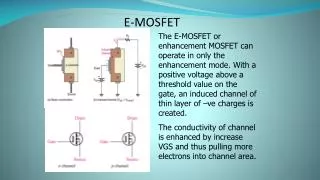
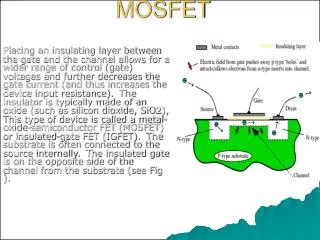
Transition between models • NMOS enhancement mode • Cut-off and Saturation/Pinch-of • Nonsaturation/Triode and Saturation/Pinch-off • PMOS enhancement mode • Cut-off and Saturation/Pinch-of • Nonsaturation/Triode and Saturation/Pinch-off
Conduction Parameters • NMOSFET • PMOSFET where:
Questions • How does VTN or VTP change with the doping concentration of the channel? • To limit the power dissipated in a FET operating in the triode region, RDSon should be as small as possible. Should VGS be large or small? • If the oxide is changed to a high K dielectric, will ID increase or decrease? To keep the drain current unchanged, should the thickness of the oxide increase or decrease? • If you fabricated a NMOS transistor in Si and GaAs with the same doping concentrations, dimensions, and same oxide material), will ID(GasAs) be larger or smaller than ID(GasAs) when VDS = VGS – VTN?