Download
1 / 32
320 likes | 420 Vues
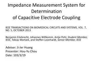
Impedance Measurement System for Determination of Capacitive Electrode Coupling. IEEE TRANSACTIONS ON BIOMEDICAL CIRCUITS AND SYSTEMS, VOL. 7, NO. 5, OCTOBER 2013

E N D
Impedance Measurement System for Determinationof Capacitive Electrode Coupling IEEE TRANSACTIONS ON BIOMEDICAL CIRCUITS AND SYSTEMS, VOL. 7, NO. 5, OCTOBER 2013 Benjamin Eilebrecht, Johannes Willkomm, Antje Pohl, Student Member, IEEE, Tobias Wartzek, and Steffen Leonhardt, Senior Member, IEEE Adviser: Ji-Jer Huang Presenter: Hou-Yu Chou Date: 103/3/19
Outline • Introduction • Materials and Methods • Results • Discussion • Conclusion & Outlook
Introduction ECG: • Advantages: better signals • Disadvantages: • skin irritations • specific preparation before measurements • limitations related to the connecting cables http://140.134.32.60:83/news/test/biotech/bei/bei.html 102/12/9
Introduction Capacitive ECG : Advantages: • does not need contact • make continuous • an office chair, a bed, a toilet seat , automobile Disadvantages: • still suffer from strong artifacts
Introduction • This paper presents a combined impedance and ECG measurement system based on capacitive electrodes,which allows simultaneous measurement of the ECG and the coupling impedance of the electrodes.
Introduction • Common ECG-systems measure the impedance between two electrodes in order to warn against a removal of electrodes. http://www.macaodaily.com/res/1/20131217/49051387214448609.jpg 103/2/26
Introduction • The combination of an impedance measurement unit and a capacitive biosignalmeasurement could be beneficial • the coupling impedance can easily result in the range of some GΩ IEEE TRANSACTIONS ON BIOMEDICAL ENGINEERING, VOL. 58, NO. 5, MAY 2011
MATERIALS & METHODS • Two units: one to measure the ECG and the other to measure the impedance • The signal separation can be done with a passive high and an active low pass filter with cut-off frequencies of 1500 and 100 Hz Bioimpedance(BIS)
MATERIALS & METHODS • MUX • Switch between the different electrodes • serve as a reference for the remaining electrodes 3-dimensional construction
MATERIALS & METHODS • Driven right leg circuit, with a negative amplification of 1000. • the common mode rejection ratio is markedly enhanced
MATERIALS & METHODS • The impedance measurement unit generally consists of a current source for injecting a current into the human body and a voltage measurement circuit to detect the voltage drop over the segment BIS Measurement Inject current Detect voltage drop Impedance
MATERIALS & METHODS • Determine both the coupling and the bioimpedance, • allowing to switch between the different electrodes was necessary
MATERIALS & METHODS • Four-pointmeasurement • a current is injected by two electrodes, whereas the voltage drop is measured by two different electrodes • Two-pointmeasurement • the same electrodes for both the injection of the current as well as for measurement of the voltage drop
MATERIALS & METHODS • EL₁ and EL₂ uses Z₁,inand Z₂,in for the current injection • Z₁,measand Z₂,measto measure the voltage drop
MATERIALS & METHODS • The ring electrode • the outer ring was used to measure the voltage drop • the inner area for current injection
MATERIALS & METHODS • Both the resistance and the capacitance can be calculated from the real and imaginary part of the coupling impedance
MATERIALS & METHODS • Before applying the system to human, the system was tested : • The bioimpedance unit was tested separately on a dummy circuit and with a galactose polymer. • calculated for different clothing materials and thicknesses http://spinoff.nasa.gov/spinoff2002/t_2.html 103/2/26
MATERIALS & METHODS • The distance between the electrodes was also tested to establish
Results • The first channel shows a flat line • In the other channels, the characteristic ECG waveforms with the representative R-peak can be seen
Results • Frequencies between 25 kHz and 500 kHz • Measurements at frequencies below 25 kHz result in significant deviations
Results • The four-point measurements of the galactose polymer • dummy resulted in impedances between 2kΩand 4kΩ, http://www.ebay.com/itm/Lifesize-Dummy-soft-MANNEQUIN-female-Dress-body-Form-Mannequin-upper-torso-bust-/281229752393 103/2/26
Results • From a combined two and four-point measurement, the real and imaginary part of the coupling impedance, using a single cotton layer as insulation material, could be calculated as:15kΩ
Results • With the electrode area A=16.6 cm² , textile thickness d = 0.5mm, dielectric constant ϵᵣ= 1 (almost air) and electrical conductivity ρ=10⁷Ωcm. • Applying these values to(1)and(2)
Discussion • According to the theory, such doubling should halve the coupling capacitance, which was not observed. • The results were achieved under controlled conditions and will be degraded in real scenarios • Even if the galactose-polymer modelwas the best choice for mimicking a real skin-electrode interface—show much lower resistive fractions of the coupling impedance than expected.
Conclusion & Outlook • The model assumption of a capacitive coupling with a resistive fraction were in the order as expected. • An extension of the system to spectrometric measurements is required and will be explored in the future. • Increasing the number of electrodes in the system will increase the order of the system of equations used to calculate the impedances
(1) (2)