Download
1 / 11
110 likes | 222 Vues
Explore the impact of non-uniformities on CVG drift and dead zones, modeling equations, strategies for drift correction, and measurement techniques for determining frequency and Q-factor mismatches in gyros.

E N D
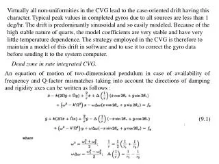
Virtually all non-uniformities in the CVG lead to the case-oriented drift having this character. Typical peak values in completed gyros due to all sources are less than 1 deg/hr. The drift is predominantly sinusoidal and so easily modeled. Because of the high stable nature of quarts, the model coefficients are very stable and have very little temperature dependence. The strategy employed in the CVG is therefore to maintain a model of this drift in software and to use it to correct the gyro data before sending it to the system computer. Dead zone in rate integrated CVG. • An equation of motion of two-dimensional pendulum in case of availability of frequency and Q-factor mismatches taking into account the directions of damping and rigidity axes can be written as follows : (9.1)
In eq. (9.1) the natural frequencies of the two modes, 1 and 2, are different, but the normal-mode axes have been assumed not to coincide with the pickoff axes x and y. is the azimuth of the 2 normal-mode axis measured from the x direction. Similarly, the principal damping time constants, iand 2are assumed different and the principal damping directions are assumed not to coincide with the pickoff axes x and y. is the azimuth of the idamping axis. The equations have been written in terms of the average and difference frequencies, and the average and difference damping constants, because in most CVGs, 1 and 2, and iand 2 are nearly equal. (and have been defined as the average and difference of the squares of the natural frequencies in order to keep the form of the equations simple while at the same time preserving their complete generality. They continue to be valid for large values of both and (1/).). Let's represent a non-uniformity of damping properties of a material in view of Fourier series expansions along circumferential coordinate of the value 1/ = : (9.2) Where o is a nominal value, i is a relative defect, i is a defect orientation. In this case equation of evolution of oscillation direction will be written as follows: (9.3)
О * Fig.9.1. Dead zone in rate integrated CVG. Frequency mismatch does not take into account in this equation. Investigation of the solution of this equation shows, that there exists dead zone at small angular rate. The dead zone threshold can be calculated as follows: (9.4) The rate integrating effect is absent. Thus, the availability of a damping non-uniformity along circumferential coordinate results in arising of a dead zone at small angular rate (see fig.9.1). It should be noted that the similar effect is observed in a ring laser gyroscope. Frequency and Q-factor Mismatches Determination There are many techniques to measure frequency and Q-factor mismatches measurement, but the technique based on measurements of amplitude-frequency (AFC) of the resonator is simple and give as information to calculate both parameters. In order to measure AFC excitation signal at frequency close to resonator natural frequency with prescribed amplitude should be applied to one on the resonator electrodes. Then, the excitation frequency changes with a small step (for quarts resonator of 0.001 Hz). The responses to this excitation are measured at two electrodes D1 and D2 located under angle 45 deg. or 22.5 deg.
Asin(2ft) D2 45o D1 Fig.9.2. Amplitude-frequency characteristic measurement A2 A1 0.707A2 0.707A1 Q1=f1/(2f1) Q2=f2/(2f2) f2 f1 f1 f2 f2 -f1 =f - frequency mismatch Q1-Q2=Q - Q-factor mismatch Fig.9.3. Frequency and Q-factor mismatches determination These two signals are stored in PC and then using, for example, MathLab calculate AFC. The measurement scheme is presented in fig. 9.2. Signal generator PC If rotate the resonator with a step 1о- 2о and each time calculate AFC and in addition phase-frequency characteristic (PhFC), the two resonant peaks would move relative to each other and there is position at which two peaks coincide, i.e. frequency mismatch f=0 and phase difference =0. It mean that direction of excitation coincides with resonator rigidity axis. There is also position when frequency mismatch f is maximum and phase difference is maximum, too.
b a A1 A1 А А A2 A A2 80 0.8 1-2 deg. 60 0.6 A1, A2,V 40 0.4 f1 f2 f f2 f 20 f 0.2 0 0 deg. 1 60 30 90 120 150 180 210 240 2 -20 -0.2 2 1 -40 -0.4 -60 -0.6 -80 -0.8 f2 f f Fig. 9.5. Phase-angle, Amplitude-angle characteristics of the resonator. Fig.9.4. Amplitude-frequency and phase-frequency characteristics of a resonator. Fig. 9.4 shows AFC an PhFC when frequency mismatch and phase difference are zero and maximum.
Thus, rotating the resonator around its axis of symmetry, phase difference and amplitudes A1and A2of signals from electrodes D1 and D2 can be measured and create dependency of a phase difference and amplitudes on orientation of resonator natural axes (fig. 9.5). Maximum and minimum on this curve determine a position of resonator natural axes. The oscillation frequency are further measured and frequency mismatch is determined. Fused quarts hemispherical resonator manufacturing technology • The hemisphere manufacturing from a quarts glass КU-1 and glass К-8 was carried out by the method of deep grinding and polishing. These processes are typical technological processes, which are well fulfilled and allow us to use machine processing. After preliminary forming spherical meniscus from cylindrical workpiece of a glass on milling machine tools with diamond cutter, they are etched in a mix of hydrofluoric and orthophosphorus acids with the purpose of stabilization of the cracked layer, which can make 150 … 250 microns. The thickness of an etched layer is ~ 50 microns. The polishing by electrolytically produced corundum will then be carried out. Thus the layer in 250 microns is removed. Removing of the cracked layer is thus achieved. However, when grinding with abrasives of different size grains, the imperfections of the certain depth are created on the surface.
Fig. 9.6. The thickness of the broken layer h is defined by h=kd, where d - maximum size of abrasive grains, k=0.21, 0.033 for silicon carbide and diamond, respectively. So at finishing operations with the help of poliarit (the size of the grains is 0.1-0.14 microns) and water, the broken layer achieves 70…100 Ao (angstrom), which are then etched in orthophosphorus acid.So, when grinding using corundum М10, the radiuses of trial elements differ from the final one by 30 microns. Then, when grinding using corundum М10 with water (with use of wet polisher), the control trial elements differ from final one by 20 microns. And only then at finishing polishing by poliarit, the control of curvature was carried out by nominal trail glass. It provides uniformity of a glass removing over all surface. Thus, polishing process is continued until one line N1, and the local deviations from sphericity did not exceed N0.2 of interference band. The roughness of the polished surface is measured with the help of profile meter. Decoding of the profile meter measurement (see Fig.9.6) shows, that height of a roughness, which is estimated by ten points (represents average between 5 highest hillocks and 5 the lowest hollows within the limits of a base line) is estimated by values:
The resonator element manufacturing - the stem - is also typical technological process, which requires consecutive application of preliminary forming according to the drawings, grinding and polishing. And for grinding and polishing with the purpose of increase of efficiency, separator method of processing is applied. For grinding metallic separator is usually used, for polishing - organic one. Thus non roundness and conicity did not exceed 0.1 microns.In order to provide a sphericity of the stem but-end surface, that should correspond to sphericity of hemisphere and also of its runout relative to a lateral surface 0.5 microns, processing of this surface is carried out with the use of the adaptation like trial glass with radius, which should correspond to the radius of an internal surface of hemisphere. In the middle of the adaptation a hole is made for tight fit of the stem.The end face is ground and polished in the adaptation using the same technological processes, as for hemisphere. However, the tolerance on coaxiality of the stem and hemisphere axes do not meet the requirements. In this connection the process of the stem manufacturing is modified, which allowed us to obtain coaxiality in compliance with the drawing requirements. The modified manufacturing process anticipates a cutting off the preform with diaD1 (~200 mm and more to process some elements simultaneously) and thickness of h1 (~25 mm) from a glass KY-1 or KB and idler preform from a glass K-8 with dia of D2(~60 mm, idler preform diameter corresponds to base of the workholder of the centering machine) and thickness of h2 (~6 mm).
С А С С С С 1'' А 1'' Autocollimator field of view А ОК С Fig.9.7. By standard grinding process we obtain parallel-sided of preform with a conicity of not greater than 10 arc sec. Then, preform and idler preform are pasted together so that general wedging did not exceed 1 arc sec. (the process was inspected by the autocollimator Fig. 9.7.). Autocollimator
Technological process of fused quarts hemispherical resonator manufacturing can be shortly gathered in the following items: 1. A 200 mm in diameter and 25 mm in thickness quartz workpiece cutoff. 2. Grinding of the workpiece surface A, executing all sequence of operations, which are envisaged by a typical technological process for grinding of optical details. 3. Grinding of the workpiece surface B, executing all sequence of operations to reduce to thickness of 23.2 mm. 4. Polishing of the workpiece surface A up to color N=1, executing all sequence of operations, which are envisaged by a typical technological process for polishing of optical details. 5. A 60 mm in diameter and 6 mm in thickness (K-8) workpiece cutoff. 6. Grinding of 60 mm in diameter workpiece surface B, executing all sequence of operations, which are envisaged by a typical technological process for grinding of optical details. 7. Grinding of 60 mm in diameter workpiece surface C up to thickness of 5 mm, executing all sequence of operations, which are used by typical technological processes for grinding of optical details. 8. Polishing of workpiece surface C up to color N=1, executing all sequence of operations, which are used by typical technological processes for grinding of optical details, fitting the wedge up to value of 10 arc sec.
9. Pasting of adaptation. The pasting is carried out under the autocollimator, overlapping flares from surfaces A and C to an accuracy of no worse, than 1arc sec. 10. Stem drilling, diameter 25 mm. 11. Grinding of a sphere of the stem end, on surface E, in accordance with stem drawings, executing all sequence of operations and reductions, which are used by typical technological processes for grinding of spherical surfaces. 12. Polishing of the sphere for diameter 25 mm, P=III cl., in accordance with stem's drawing (N=2), executing all sequence of operations and reductions, which are envisaged by typical technological processes for polishing of spherical surfaces. 13. Centering of a sphere in the centering cartridge (fixation is carried out on a surface С with a gum). Provide accuracy of centering 1 … 3 microns, conduct control of accuracy of centering by standard methods. 14. Turning of diameter 6.8 –0.02 mm along length of 25 mm. 15. Peeling off the adaptation. 16. Cutting the stem facets in accordance with drawing. 17. Putting stem and meniscus on an optical contact. 18. A sintering resonator elements. 19. Cleaning the resonator with the use of standard techniques of cleaning off-the-shelf optical details. 20. Finishing chemical etching of the resonator.