Chapter 4 Network Layer
Chapter 4 Network Layer. A note on the use of these ppt slides:

Chapter 4 Network Layer
E N D
Presentation Transcript
Chapter 4Network Layer • A note on the use of these ppt slides: • We’re making these slides freely available to all (faculty, students, readers). They’re in PowerPoint form so you can add, modify, and delete slides (including this one) and slide content to suit your needs. They obviously represent a lot of work on our part. In return for use, we only ask the following: • If you use these slides (e.g., in a class) in substantially unaltered form, that you mention their source (after all, we’d like people to use our book!) • If you post any slides in substantially unaltered form on a www site, that you note that they are adapted from (or perhaps identical to) our slides, and note our copyright of this material. Thanks and enjoy! JFK/KWR • All material copyright 1996-2007 • J.F Kurose and K.W. Ross, All Rights Reserved Computer Networking: A Top Down Approach 4th edition. Jim Kurose, Keith RossAddison-Wesley, July 2007. Network Layer
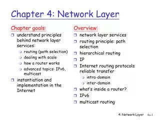
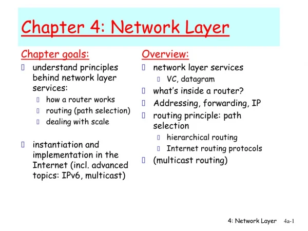
4. 1 Introduction 4.2 Virtual circuit and datagram networks 4.3 What’s inside a router 4.4 IP: Internet Protocol Datagram format IPv4 addressing ICMP IPv6 4.5 Routing algorithms Link state Distance Vector Hierarchical routing 4.6 Routing in the Internet RIP OSPF BGP 4.7 Broadcast and multicast routing Chapter 4: Network Layer Network Layer
u v destinationhops u 1 v 2 w 2 x 3 y 3 z 2 w x z y C A D B RIP ( Routing Information Protocol) • distance vector algorithm • included in BSD-UNIX Distribution in 1982 • distance metric: # of hops (max = 15 hops) From router A to subnets: Network Layer
RIP advertisements • distance vectors: exchanged among neighbors every 30 sec via Response Message (also called advertisement) • each advertisement: list of up to 25 destination subnets within AS Network Layer
RIP: Example z w x y A D B C Destination Network Next Router Num. of hops to dest. w A 2 y B 2 z B 7 x -- 1 …. …. .... Routing/Forwarding table in D Network Layer
z w x y A D B C RIP: Example Dest Next hops w - 1 x - 1 z C 4 …. … ... Advertisement from A to D Destination Network Next Router Num. of hops to dest. w A 2 y B 2 z B A 7 5 x -- 1 …. …. .... Routing/Forwarding table in D Network Layer
RIP: Link Failure and Recovery If no advertisement heard after 180 sec --> neighbor/link declared dead • routes via neighbor invalidated • new advertisements sent to neighbors • neighbors in turn send out new advertisements (if tables changed) • link failure info quickly (?) propagates to entire net • poison reverse used to prevent ping-pong loops (infinite distance = 16 hops) Network Layer
routed routed RIP Table processing • RIP routing tables managed by application-level process called route-d (daemon) • advertisements sent in UDP packets, periodically repeated Transprt (UDP) Transprt (UDP) network forwarding (IP) table network (IP) forwarding table link link physical physical Network Layer
4. 1 Introduction 4.2 Virtual circuit and datagram networks 4.3 What’s inside a router 4.4 IP: Internet Protocol Datagram format IPv4 addressing ICMP IPv6 4.5 Routing algorithms Link state Distance Vector Hierarchical routing 4.6 Routing in the Internet RIP OSPF BGP 4.7 Broadcast and multicast routing Chapter 4: Network Layer Network Layer
OSPF (Open Shortest Path First) • “open”: publicly available • uses Link State algorithm • LS packet dissemination • topology map at each node • route computation using Dijkstra’s algorithm • OSPF advertisement carries one entry per neighbor router • advertisements disseminated to entire AS (via flooding) • carried in OSPF messages directly over IP (rather than TCP or UDP Network Layer
OSPF “advanced” features (not in RIP) • security: all OSPF messages authenticated (to prevent malicious intrusion) • multiple same-cost paths allowed (only one path in RIP) • For each link, multiple cost metrics for different TOS (e.g., satellite link cost set “low” for best effort; high for real time) • integrated uni- and multicast support: • Multicast OSPF (MOSPF) uses same topology data base as OSPF • hierarchical OSPF in large domains. Network Layer
Hierarchical OSPF Network Layer
Hierarchical OSPF • two-level hierarchy: local area, backbone. • Link-state advertisements only in area • each nodes has detailed area topology; only know direction (shortest path) to nets in other areas. • area border routers:“summarize” distances to nets in own area, advertise to other Area Border routers. • backbone routers: run OSPF routing limited to backbone. • boundary routers: connect to other AS’s. Network Layer
4. 1 Introduction 4.2 Virtual circuit and datagram networks 4.3 What’s inside a router 4.4 IP: Internet Protocol Datagram format IPv4 addressing ICMP IPv6 4.5 Routing algorithms Link state Distance Vector Hierarchical routing 4.6 Routing in the Internet RIP OSPF BGP 4.7 Broadcast and multicast routing Chapter 4: Network Layer Network Layer
Internet inter-AS routing: BGP • BGP (Border Gateway Protocol):the de facto standard • BGP provides each AS a means to: • Obtain subnet reachability information from neighboring ASs. • Propagate reachability information to all AS-internal routers. • Determine “good” routes to subnets based on reachability information and policy. • allows subnet to advertise its existence to rest of Internet: “I am here” Network Layer
2c 2b 3c 1b 1d 1c BGP basics • pairs of routers (BGP peers) exchange routing info over semi-permanent TCP connections: BGP sessions • BGP sessions need not correspond to physical links. • when AS2 advertises a prefix to AS1: • AS2 promises it will forward datagrams towards that prefix. • AS2 can aggregate prefixes in its advertisement eBGP session iBGP session 3a 3b 2a AS3 AS2 1a AS1 Network Layer
2c 2b 3c 1b 1d 1c Distributing reachability info • using eBGP session between 3a and 1c, AS3 sends prefix reachability info to AS1. • 1c can then use iBGP do distribute new prefix info to all routers in AS1 • 1b can then re-advertise new reachability info to AS2 over 1b-to-2a eBGP session • when router learns of new prefix, it creates entry for prefix in its forwarding table. eBGP session iBGP session 3a 3b 2a AS3 AS2 1a AS1 Network Layer
Path attributes & BGP routes • advertised prefix includes BGP attributes. • prefix + attributes = “route” • two important attributes: • AS-PATH: contains ASs through which prefix advertisement has passed: e.g, AS 67, AS 17 • NEXT-HOP: indicates specific internal-AS router to next-hop AS. (may be multiple links from current AS to next-hop-AS) • when gateway router receives route advertisement, uses import policy to accept/decline. Network Layer
BGP route selection • router may learn about more than 1 route to some prefix. Router must select route. • elimination rules: • local preference value attribute: policy decision • shortest AS-PATH • closest NEXT-HOP router: hot potato routing • additional criteria Network Layer
BGP messages • BGP messages exchanged using TCP. • BGP messages: • OPEN: opens TCP connection to peer and authenticates sender • UPDATE: advertises new path (or withdraws old) • KEEPALIVE keeps connection alive in absence of UPDATES; also ACKs OPEN request • NOTIFICATION: reports errors in previous msg; also used to close connection Network Layer
legend: provider B network X W A customer network: C Y BGP routing policy • A,B,C are provider networks • X,W,Y are customer (of provider networks) • X is dual-homed: attached to two networks • X does not want to route from B via X to C • .. so X will not advertise to B a route to C Network Layer
legend: provider B network X W A customer network: C Y BGP routing policy (2) • A advertises path AW to B • B advertises path BAW to X • Should B advertise path BAW to C? • No way! B gets no “revenue” for routing CBAW since neither W nor C are B’s customers • B wants to force C to route to w via A • B wants to route only to/from its customers! Network Layer
Why different Intra- and Inter-AS routing ? Policy: • Inter-AS: admin wants control over how its traffic routed, who routes through its net. • Intra-AS: single admin, so no policy decisions needed Scale: • hierarchical routing saves table size, reduced update traffic Performance: • Intra-AS: can focus on performance • Inter-AS: policy may dominate over performance Network Layer
4. 1 Introduction 4.2 Virtual circuit and datagram networks 4.3 What’s inside a router 4.4 IP: Internet Protocol Datagram format IPv4 addressing ICMP IPv6 4.5 Routing algorithms Link state Distance Vector Hierarchical routing 4.6 Routing in the Internet RIP OSPF BGP 4.7 Broadcast and multicast routing Chapter 4: Network Layer Network Layer
duplicate creation/transmission duplicate duplicate in-network duplication sourceduplication R4 R2 R4 R2 R3 R3 R1 R1 Broadcast Routing • deliver packets from source to all other nodes • source duplication is inefficient: • source duplication: how does source determine recipient addresses? Network Layer
In-network duplication • flooding: when node receives brdcst pckt, sends copy to all neighbors • Problems: cycles & broadcast storm • controlled flooding: node only brdcsts pkt if it hasn’t brdcst same packet before • Node keeps track of pckt ids already brdcsted • Or reverse path forwarding (RPF): only forward pckt if it arrived on shortest path between node and source • spanning tree • No redundant packets received by any node Network Layer
(b) Broadcast initiated at D (a) Broadcast initiated at A A A D D G G B B E E F F c c Spanning Tree • First construct a spanning tree • Nodes forward copies only along spanning tree Network Layer
A A D D G G B E B E F F c c Spanning Tree: Creation • Center node • Each node sends unicast join message to center node • Message forwarded until it arrives at a node already belonging to spanning tree 3 4 2 5 1 • Stepwise construction of spanning tree (b) Constructed spanning tree Network Layer
Source-based trees Multicast Routing: Problem Statement • Goal: find a tree (or trees) connecting routers having local mcast group members • tree: not all paths between routers used • source-based: different tree from each sender to rcvrs • shared-tree: same tree used by all group members Shared tree
Approaches for building mcast trees Approaches: • source-based tree: one tree per source • shortest path trees • reverse path forwarding • group-shared tree: group uses one tree • minimal spanning (Steiner) • center-based trees …we first look at basic approaches, then specific protocols adopting these approaches
1 i 5 4 3 6 2 Shortest Path Tree • mcast forwarding tree: tree of shortest path routes from source to all receivers • Dijkstra’s algorithm S: source LEGEND R1 R4 router with attached group member R2 router with no attached group member R5 link used for forwarding, i indicates order link added by algorithm R3 R7 R6
Reverse Path Forwarding if (mcast datagram received on incoming link on shortest path back to center) then flood datagram onto all outgoing links else ignore datagram • rely on router’s knowledge of unicast shortest path from it to sender • each router has simple forwarding behavior:
Reverse Path Forwarding: example S: source LEGEND R1 R4 router with attached group member R2 router with no attached group member R5 datagram will be forwarded R3 R7 R6 datagram will not be forwarded • result is a source-specific reverse SPT • may be a bad choice with asymmetric links
Reverse Path Forwarding: pruning • forwarding tree contains subtrees with no mcast group members • no need to forward datagrams down subtree • “prune” msgs sent upstream by router with no downstream group members LEGEND S: source R1 router with attached group member R4 router with no attached group member R2 P P R5 prune message links with multicast forwarding P R3 R7 R6
Shared-Tree: Steiner Tree • Steiner Tree: minimum cost tree connecting all routers with attached group members • problem is NP-complete • excellent heuristics exists • not used in practice: • computational complexity • information about entire network needed • monolithic: rerun whenever a router needs to join/leave
Center-based trees • single delivery tree shared by all • one router identified as “center” of tree • to join: • edge router sends unicast join-msg addressed to center router • join-msg “processed” by intermediate routers and forwarded towards center • join-msg either hits existing tree branch for this center, or arrives at center • path taken by join-msg becomes new branch of tree for this router
Center-based trees: an example Suppose R6 chosen as center: LEGEND R1 router with attached group member R4 3 router with no attached group member R2 2 1 R5 path order in which join messages generated R3 1 R7 R6
Internet Multicasting Routing: DVMRP • DVMRP: distance vector multicast routing protocol, RFC1075 • flood and prune: reverse path forwarding, source-based tree • RPF tree based on DVMRP’s own routing tables constructed by communicating DVMRP routers • no assumptions about underlying unicast • initial datagram to mcast group flooded everywhere via RPF • routers not wanting group: send upstream prune msgs
DVMRP: continued… • soft state: DVMRP router periodically (1 min.) “forgets” branches are pruned: • mcast data again flows down unpruned branch • downstream router: reprune or else continue to receive data • routers can quickly regraft to tree • following IGMP join at leaf • odds and ends • commonly implemented in commercial routers • Mbone routing done using DVMRP
Tunneling Q: How to connect “islands” of multicast routers in a “sea” of unicast routers? logical topology physical topology • mcast datagram encapsulated inside “normal” (non-multicast-addressed) datagram • normal IP datagram sent thru “tunnel” via regular IP unicast to receiving mcast router • receiving mcast router unencapsulates to get mcast datagram
not dependent on any specific underlying unicast routing algorithm (works with all) two different multicast distribution scenarios : PIM: Protocol Independent Multicast • Dense: • group members densely packed, in “close” proximity. • bandwidth more plentiful • Sparse: • # networks with group members small wrt # interconnected networks • group members “widely dispersed” • bandwidth not plentiful
Dense group membership by routers assumed until routers explicitly prune data-driven construction on mcast tree (e.g., RPF) bandwidth and non-group-router processing profligate Sparse: no membership until routers explicitly join receiver- driven construction of mcast tree (e.g., center-based) bandwidth and non-group-router processing conservative Consequences of Sparse-Dense Dichotomy:
PIM- Dense Mode • flood-and-prune RPF, similar to DVMRP but • underlying unicast protocol provides RPF info for incoming datagram • less complicated (less efficient) downstream flood than DVMRP reduces reliance on underlying routing algorithm • has protocol mechanism for router to detect it is a leaf-node router
center-based approach router sends join msg to rendezvous point (RP) intermediate routers update state and forward join after joining via RP, router can switch to source-specific tree increased performance: less concentration, shorter paths PIM - Sparse Mode R1 R4 join R2 join R5 join R3 R7 R6 all data multicast from rendezvous point rendezvous point
sender(s): unicast data to RP, which distributes down RP-rooted tree RP can extend mcast tree upstream to source RP can send stop msg if no attached receivers “no one is listening!” PIM - Sparse Mode R1 R4 join R2 join R5 join R3 R7 R6 all data multicast from rendezvous point rendezvous point
4. 1 Introduction 4.2 Virtual circuit and datagram networks 4.3 What’s inside a router 4.4 IP: Internet Protocol Datagram format IPv4 addressing ICMP IPv6 4.5 Routing algorithms Link state Distance Vector Hierarchical routing 4.6 Routing in the Internet RIP OSPF BGP 4.7 Broadcast and multicast routing Chapter 4: summary Network Layer