Beam diagnostics
Beam diagnostics. What to measure. Intensity From very weak to very intense beams aA to mA Profile From very low energy to high energy From very weak to very intense beams Timing Noise from the accelerator RF Same frequency as for the beam pulses. Beam transformers.


Beam diagnostics
E N D
Presentation Transcript
What to measure • Intensity • From very weak to very intense beams • aA to mA • Profile • From very low energy to high energy • From very weak to very intense beams • Timing • Noise from the accelerator RF • Same frequency as for the beam pulses
In order for the transformer to see the magnetic field produced by the beam, • it must be mounted over a ceramic insert in the metallic vacuum chamber. • The ferromagnetic core is wound of high permeability metal tape or made of ferrite, to avoid eddy currents. • Bandwidths exceeding 100 MHz can thus be achieved. • An idealized transformer with a secondary winding of inductance L and connected to an infinite impedance would deliver as signal a voltage
The signal now shows a much more useful behaviour (Fig. 4). Provided the length of a beam bunch is longer than the transformer's rise time and shorter than its droop time, the signal will be a good reproduction of the bunch shape.
For a beam circulating in a machine, the succession of bunches seen by the transformer will be much longer than its droop time. Therefore, to obtain a signal representing the beam intensity, one has to electronically treat the transformer's signal such that the effective droop time is much longer than the time that the beam circulates. At the same time, this increases the signal rise time, so that the bunch structure will disappear. Such a treatment is often called a "low pass" or "integration". Figure 6 shows three commonly used methods.
Wall-current monitors One may want to observe the bunch shape at frequencies far beyond the few 100 MHz accessible with beam transformers. The bunches may be very short, as is often the case with electrons or positrons, or they may have a structure in their line density, caused by intentional processes or by instabilities. Wall-current monitors with a bandwidth of several GHz have been built. Their principle is quite simple (Fig. 8a) :
A modulated beam current Ib is accompanied by a "wall current", IW, which it induces in the vacuum chamber, of equal magnitude and opposite direction. • An insulating gap forces the wall current to pass through the impedance of a coaxial cable. The gap may also be bridged with resistors, across which a voltage is picked up. • To avoid perturbation through circumferential modes, the wall current (or the gap voltage) is picked up at several points around the circumference and summed. When the beam is not at the centre of the vacuum chamber, the wall current will be unequally distributed around the circumference of the chamber. Separate pick-up and separate observation (Fig. 8b) will thus also show the beam position with GHz bandwidth.
A conducting shield must be placed around a wall-current monitor. • Without it, troublesome electromagnetic radiation from the beam would leak out through the gap and the monitor itself would be perturbed from the outside. • The shield constitutes a short-circuit at low frequencies and thus severely limits the lower end of the monitor's bandwidth. • Loading the volume of the shield with ferrite increases the inductance and the cut-off can be lowered to some 100 kHz, sufficient for undifferentiated observation of bunch shape in most accelerators.
Position pick-up monitors (PU) Transverse beam position electrostatic magnetic electromagnetic
The beam will induce electric charges on the metallic electrodes, more on the one to which it is closer, sum remaining constant. The induced charges can be carried away for measurement into a low-impedance circuit or be sensed on a high impedance as a voltage on the capacity between the electrode and the surrounding vacuum chamber.
In electron and positron machines, no electrodes can be tolerated in the mid-plane : there they would be hit by the synchrotron radiation and the resulting secondary electron emission would perturb the signal. So-called "button" electrodes are used, housed in recesses
Faraday cup • Beam intensity measurement (electric current) • Stop the beam and measure the current
The beam must be STOPPED in the cup • The range of the particle must be less than the thickness of the cup bottom. Range of protons in Cu: Very important: Do not let secondary electrons escape from the FC nor let secondary electrons from e.g. a collimator hit the FC!
COL e- suppressor Note the diameters! e- beam FC -U A
Secondary-emission monitors (SEM) Under the impact of the beam particles on some solid material electrons are liberated from the surface, thus producing a flow of current.
The provision of a "clearing field" of a few 100 V/cm is essential to ensure that the liberated electrons are rapidly cleared away. Otherwise, an electron cloud may form over the foil surface and impede further emission.
Multi-wire chambers Electrons produced in the gas by the passing beam particles will travel towards the nearest wire. In the high gradient close to the wire they experience strong acceleration and create an avalanche. A wire chamber can be used in counting or in proportional mode. The distribution of counting rate or signal height over the wires represents the beam profile. More about this by Grigori Tiourine
This is a gas-filled, thin-walled chamber with a collector electrode inside. Particles passing through it will ionize the gas, the ions will travel towards the cathode, the electrons towards the anode and a current can be measured (Fig. 20). The voltage should be in the "plateau" region where all charges are collected but no avalanche occurs.
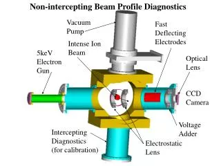
Residual-gas monitors When neither the residual gas pressure nor the beam intensity are too low, ionization of the "natural" residual gas may supply electrons in sufficient number and a gas curtain is not needed. 1D projection or 2D profile
The Ionization Beam Scanner (IBS) is a further device relying on residual gas. It employs a time-varying electric and a static magnetic field, at right angles to each other and to the beam, to guide the ionization electrons towards a collector or electron multiplier. Although a precise instrument for low intensity beams, the IBS is too easily perturbed by the space charge fields of intense beams. Instead of collecting electrons from the ionization, one can also observe the light from de-excitation of the residual gas atoms. This is achieved more easily at the low energies of a pre-injector (500-800 keV) combined with the prevalent modest vacuum.
Scintillator screens Scintillators were the first particle detectors, a century ago.
The most common scintillator used to be ZnS powder which, with some binder, was painted onto a metal plate. Such screens deliver green light and have high efficiency but are unfit for use in high vacuum and are burnt out at some 1014 protons/cm2 at GeV energies. A great step forward was the formation of thick Al203 layers on aluminium plates under simultaneous doping with Cr. Chemically, this is the same as ruby and the light emitted is red. These screens are fit for ultra high vacuum and have a long lifetime (1020 to 1021 p/cm2 at 50 MeV).
Choise of the TV camera important. Often it needs to be radiation resistant. The model developed at CERN uses nuvistors and stands 108 Rad. Ordinary lenses turn brown under radiation. Catadioptric optics do a bit better but when radiation is really a problem, one has to buy expensive lenses developed for use in reactors.
For very weak beams a combination image intensifier - Vidicon is used. Also, CCD-cameras offer high sensitivity, but are little resistant to radiation. • Help: • Use telescopic lens and cameras inside radiation shield • Use fiber optics
Comments/hints for current measurement • Remember grounding • Sometimes the beam tube has been insulated from the main beam line insulator Electrically connected to Cyclotron/ion source To current meter
Very small currents with particle detectors • aA • Otherwise with a Faraday cup (proper amplifiers) • 10 pA and more • Small currents • problem with noise • Very high currents • Remember to cool the FC (and preceding collimator) with water • The region between particle detectors and a current meter is difficult. • Be sure that high current does not hit (kill) the particle detector
Emittance measurement Emittance ellipse describes the area/volume in the phase space, which the beam occupies. Emittance E is the area of the ellipse (E = pe). Twiss parameters a, b, g
x’0b x1b x’0a x1a x0 l
Measure x0, x1a and x1b • Get points x’0a and x’0b • Scan x0 and get the ellipse contour x1a x1b x1
How to measure x1? • Scan a slit at x1 and measure current with a Faraday cup • Mechanical (both x0 and x1) • Slow • Scan the beam direction by bending the beam • With E or B • Faster (only x0 mechanical) • May need high voltages for a high energy beam/large divergence