Download
1 / 39
400 likes | 568 Vues
48th ICFA Advanced Beam Dynamics Workshop on Future Light Sources. Studies of cERL injector. Thursday, March 4, 2010 SLAC National Accelerator Laboratory Menlo Park, California Tsukasa Miyajima 7 th division, Accelerator Laboratory, KEK, High Energy Accelerator Research Organization.

E N D
48th ICFA Advanced Beam Dynamics Workshop on Future Light Sources Studies of cERL injector Thursday, March 4, 2010SLAC National Accelerator LaboratoryMenlo Park, California Tsukasa Miyajima 7th division, Accelerator Laboratory, KEK, High Energy Accelerator Research Organization Contents Outline of compact ERL injector Beam Simulation to optimize beamline parameters Test beamline for cERL injector Future issues Summary
ERL collaboration team • High Energy Accelerator Research Organization (KEK) • M. Akemoto, T. Aoto, D. Arakawa, S. Asaoka, A. Enomoto, S. Fukuda, K. Furukawa, T. Furuya, K. Haga, K. Hara, K. Harada, T. Honda, Y. Honda, T. Honma, T. Honma, K. Hosoyama, M. Isawa, E. Kako, T. Kasuga, H. Katagiri, H. Kawata, Y. Kobayashi, Y. Kojima, T. Matsumoto, H. Matsushita, S. Michizono, T. Mitsuhashi, T. Miura, T. Miyajima, H. Miyauchi, S. Nagahashi, H. Nakai, H. Nakajima, E. Nakamura, K. Nakanishi, K. Nakao, T. Nogami, S. Noguchi, S. Nozawa, T. Obina, S. Ohsawa, T. Ozaki, C. Pak, H. Sakai, S. Sakanaka, H. Sasaki, Y. Sato, K. Satoh, M. Satoh, T. Shidara, M. Shimada, T. Shioya, T. Shishido, T. Suwada, T. Takahashi, R. Takai, T. Takenaka, Y. Tanimoto, M. Tobiyama, K. Tsuchiya, T. Uchiyama, A. Ueda, K. Umemori, K. Watanabe, M. Yamamoto, Y. Yamamoto, S. Yamamoto, Y. Yano, M. Yoshida • Japan Atomic Energy Agency (JAEA) • R. Hajima, R. Nagai, N. Nishimori, M. Sawamura • Institute for Solid State Physics (ISSP), University of Tokyo • N. Nakamura, I Itoh, H. Kudoh, T. Shibuya, K. Shinoe, H. Takaki • UVSOR, Institute for Molecular Science • M. Katoh, M. Adachi • Hiroshima University • M. Kuriki, H. Iijima, S. Matsuba • Nagoya University • Y. Takeda, T. Nakanishi, M. Kuwahara, T. Ujihara, M. Okumi • National Institute of Advanced Industrial Science and Technology (AIST) • D. Yoshitomi, K. Torizuka • JASRI/SPring-8 • H. Hanaki FLS2010, March 1-5, 2010, SLAC National Accelerator Laboratory
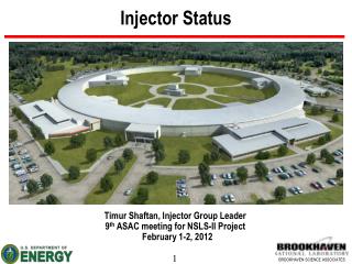
Compact ERL The Compact ERL for demonstrating ERL technologies Before constructing large-scale ERL facility, we need to demonstrate the generation of ultra-low emittance beams using key devices. Parameters of the Compact ERL East Counter Hall 100 m FLS2010, March 1-5, 2010, SLAC National Accelerator Laboratory
cERL injector • cERL injector: to generate electron beam with lower emittance and shorter bunch length Parameters of the Compact ERL Injector Photo cathode DC gun Super conducting cavity (2 cell, 3 modules) ERL Injector Merger section Compact ERL FLS2010, March 1-5, 2010, SLAC National Accelerator Laboratory
Components in ERL injector • Photo cathode DC gun • Gun, HV power supply, driving laser system • Solenoid magnet • To compensate emittance • Bunching cavity • Normal conducting cavity for bunching • SRF cavities • 2-cell, 3 modules • Quadrupole magnets • To adjust CS parameters before merger section • Merger section • To merge injected beam into return loops ② ① ⑤ ⑥ ④ ③ 500 keV 5 – 10 MeV Beam energy: Space charge effect is dominant. FLS2010, March 1-5, 2010, SLAC National Accelerator Laboratory
Cross sections and field maps (a) Cross sections DC gun Solenoid magnet Bunching cavity SRF cavity (b) 1D field map FLS2010, March 1-5, 2010, SLAC National Accelerator Laboratory
Physics in ERL injector Space charge effect (Coulomb force between electrons) Solenoid focusing (Emittance compensetion) RF kick in RF cavity Higher order dispersion in merger section Coherent Synchrotron Radiation (CSR) in merger section Response time of photo cathode(It generates tail of emission.) These effects combine in the ERL injector. To obtain high quality beam at the exit of merger, optimization of beamline parameters is required. Method to research the beam dynamics: Macro particle tracking simulation with space charge effect is used. • The simulation code have to include • External electric and magnetic field, • Space charge effect (3D space charge). FLS2010, March 1-5, 2010, SLAC National Accelerator Laboratory
Beam Simulation • Purpose of simulation • To find optimum beamline parameters, i.e. magnet strength, RF phase, etc., with lower emittance and shorter bunch length. • To calculate beam parameters, i.e. emittance, beam size, etc., to design components in ERL injector. Initial distribution on cathode:beer-can • Particle tracking code:GPT(General Particle Tracer)[1] • Space charge calculation:3D mesh based method • Initial particle distribution:beer-can • No CSR effect in merger section d = 4 sx Dt=sqrt(12)*st [1] Pulsar Physics, http://www.pulsar.nl/gpt/index.html FLS2010, March 1-5, 2010, SLAC National Accelerator Laboratory
Multi objective optimization • To minimize both emittance and bunch length at 1 m from the exit of merger • Multi objective method is used[2] Results of optimization Bunch lengthvs. normalized rmsemittance For shorter bunch length, emittance is larger than the case of longer bunch length. Layout of beamline Beam parameters are calculated at 1 m from exit of merger. Normalized rmsemittance 0.4 ~ 0.5 mm mrad • Free parameters in the optimization • Initial laser radius (mm) • Initial laser pulse length (ps) • Magnetic field of 1st solenoid • Electric field of bunching cavity • Magnetic field of 2nd solenoid • Electric field and phase of SRF1 • Electric field and phase of SRF2 • Electric field and phase of SRF3 • Magnetic fields of 5 quadrupoles Number of free parameters: 16 Minimize both emittance and bunch length. (2 objects optimization) [2] Ivan V. Bazarov and Charles K. Sinclair , Phys. Rev. ST Accel. Beams 8, 034202 (2005). FLS2010, March 1-5, 2010, SLAC National Accelerator Laboratory
Dependence on number of particles • In the macro particle tracking simulation, we can not avoid the effect of number of macro particles, because we can not simulate actual number of electrons. • To obtain more accurate results, • In early optimization : 5k particles (to save CPU time) • But, the accuracy is not so good for 5 k particles • In final optimization, we optimize beam line parameters with 200 k particles after the early optimization with 5k particles. For 77 pC, actual number of electrons is 480 M particles. Normalized rms emittance Rms beam size At lease Nps > 100 k FLS2010, March 1-5, 2010, SLAC National Accelerator Laboratory
Optimum beamline parameters • Beam line parameters for high current mode with 80 pC/bunch, which give bunch length of 0.63 mm and normalized rms emittance of 0.56 mm mrad *:RF phase from maximum acceleration. FLS2010, March 1-5, 2010, SLAC National Accelerator Laboratory
Time evolution of beam parameters (2) Rms beam size and bunch length (1) Normalized rms emittance (3) Kinetic energy and energy spread Normalized rmsemittance: 0.56 mm mrad Bunch length:0.63 mm Kinetic energy:8.2 MeV Related rms energy spread: 0.23 % FLS2010, March 1-5, 2010, SLAC National Accelerator Laboratory
Time evolution of phase space distribution cathode Bunch charge: -80 pC/bunch Normalized rmsemittance: 0.56 mm mrad Bunch length:0.63 mm Kinetic energy:8.2 MeV 1st solenoid Exit of merger 5 quadrupoles Bunching cavity 2nd solenoid Exit of SRF FLS2010, March 1-5, 2010, SLAC National Accelerator Laboratory
Summary of optimization • We have designed the injector for the cERL and carried out beam dynamics simulation using the particle tracking code with 3D space charge effect. • To optimize the beamline parameters, we are using multi objective method and cluster linux machine. • At the end of the injector, we have obtained the emittance of 0.56 mm·mrad with the bunch length of 0.63 mm for the high current operation mode (80 pC/bunch). FLS2010, March 1-5, 2010, SLAC National Accelerator Laboratory
Gun test beamline for cERL injector • Purpose of test beam line • To gain operation experience of the low energy beam. • To evaluate performance of the DC guns by an additional diagnostic line to measure emittance and bunch length • To develop a new 500 kV gun, diagnostic system and the injector line used at cERL. 2010- middle of 2011: 200 kV gun 2011 - : new 500 kV gun NPES3, 200 kV gun transferred from Nagoya university at May 2009. Gun Test beamline Laser system Test area for 500 kV gun FLS2010, March 1-5, 2010, SLAC National Accelerator Laboratory
Layout of gun test beamline 5th view screen 4th solenoid 3rd solenoid 2nd slit (horizontal) 1st slit (horizontal) 1st slit (vertical) 2nd slit (vertical) 1st solenoid 2nd solenoid Beam dump 1st view screen 2nd view screen 3rd view screen 4th view screen Bending magnet deflector The same layout as cERL injector Beam diagnostic line(emittance, Bunch length measurements) Beam dump line FLS2010, March 1-5, 2010, SLAC National Accelerator Laboratory
Components for gun test facility • We are constructing gun test facility with 200 kV photo cathode DC gun in AR south experimental hall, KEK. From this spring, we are going to start beam running. 2nd solenoid From Gun e- To SRF cavity e- Bunching cavity 2nd view screen monitor Two solenoid magnets 1st view screen monitor 1st solenoid Laser chamber The layout of the cERL injector before SRF cavity. In the first test, the bunching cavity is not installed. Laser chamber FLS2010, March 1-5, 2010, SLAC National Accelerator Laboratory
Beam dynamics of gun test beamline Result of optimization • Initial parameters at point A: • Radius of initial particle distribution: 1.91 mm • Laser pulse full width:41.5 ps • 1st Solenoid:0.039 T • Bunching cavity: 0 kV • 2nd Solenoid:0.026 T A At 1st slit, Emittance: 0.42 mm mrad Bunch length: 6.7 mm Gun 1st view screen 2nd view screen 1st slit 3rd view screen FLS2010, March 1-5, 2010, SLAC National Accelerator Laboratory
Future issues • Beamline parameter optimization for XFEL-O with 20 pC, 0.1 mm mrad. • To obtain lower emittance, can we increase the voltage of the photo cathode gun over 500 kV? • Beam optics matching with return loop • Establish the beam tuning method in the commissioning. • Beam simulation with CSR and Space charge effect in the merger section. We developed CSR routine, which is effective in lower energy beam. R. Hajima and N. Nishimori (JAEA), Proc. FEL2008, pp. 87-89. cf. K.-J. Kim et al., PRL 100, 244802 (2008). FLS2010, March 1-5, 2010, SLAC National Accelerator Laboratory
Beam simulation for XFEL-O • Target values for XFEL-O: < 0.1 mm mrad, 20 pC/bunch, 2 ps bunch length Layout of beamline Preliminary results Bunch charge: 20 pC/bunch Gun voltage: 500 kV or 600 kV (1) 0.6 mm (2 ps) bunch length enx = 0.14 mm mrad with 500 kV enx = 0.13 mm mrad with 600 kV (2) 0.9 mm (3 ps) bunch length enx = 0.12 mm mrad with 500 kV enx = 0.11 mm mrad with 600 kV Beam parameters are calculated at 1 m from exit of merger. Preliminary results It is not so far from target value for XFEL-O. We are going to investigate the effect of gun voltage. FLS2010, March 1-5, 2010, SLAC National Accelerator Laboratory
Summary • Beam dynamics simulation for the cERL has been carried out using 3D space charge macro-particle tracking code. • To find the optimum parameters, which give minimum emittance and bunch length, the parameter optimization has been carried. • For high current mode with 80 pC/bunch, we obtained the minimum emittance of 0.56 mm mrad with the bunch length of 0.63 mm. • To design ERL components (Gun, Buncher, SRF cavities, solenoid, alignment, etc.), we have studied tolerances of errors in ERL injector. • To evaluate performance of the DC guns, we are developing the gun test beamline in the PF-AR south experimental hall. • From the early part of March, we are going to start beam running in the gun test beamline using NPES3 200kV DC photo cathode gun. • For XFEL-O, the minimun emittance is calculating with 20 pC/bunch. • So far, we have obtained the minimum emittance of 0.13 mm mrad with the bunch length of 0.6 mm (2 ps) and the gun voltage of 600 kV. FLS2010, March 1-5, 2010, SLAC National Accelerator Laboratory
Backup slides FLS2010, March 1-5, 2010, SLAC National Accelerator Laboratory
Effect of gun voltage Preliminary results Bunch charge: 20 pC/bunch Gun voltage: 500 kV or 600 kV At exit of merger (1) 0.6 mm (2 ps) bunch length enx = 0.14 mm mrad with 500 kV enx = 0.13 mm mrad with 600 kV (2) 0.9 mm (3 ps) bunch length enx = 0.12 mm mrad with 500 kV enx = 0.11 mm mrad with 600 kV Results of Gun and solenoid beamline FLS2010, March 1-5, 2010, SLAC National Accelerator Laboratory
How to optimize the parameters? • Macro particle tracking simulation with space charge requires longer CPU time. • In the optimization, tracking simulation is repeated to search optimum parameter. Therefore, the calculation time to optimize the parameters is too long. • To save the calculation time, efficient optimization method is required. • In order to reduce the calculation time, we use • Multi objective method [2] as an efficient method, and • Cluster linux computer, which have 80 CPUs. The parallel 80 jobs, which have different beamline parameters, can be executed on the cluster computer. • Two objects in the optimization • Emittance • Bunch length To minimize emittance and bunch length Trade-off solutions [2] Ivan V. Bazarov and Charles K. Sinclair , Phys. Rev. ST Accel. Beams 8, 034202 (2005). FLS2010, March 1-5, 2010, SLAC National Accelerator Laboratory
Results of optimization (1) Sector type(bending angles:-19, 22, -19degree) Normalized rms emittance 0.4 ~ 0.5 mm mrad (2) Rectangular type(bending angles:-16, 16, -16degree) Emittance growth caused by space charge dispersion. The rectangular type gives smaller emittance than the sector type. It seems that stronger longitudinal space charge dispersion in the sector type causes the difference of emittance, because the bending angle of the bending magnet in the sector type (19◦ or 22◦) are larger than one in the rectangular type (16◦). • Maximum emittance growth • Minimum emittance growth • Emittance growth depends on space charge dispersion. FLS2010, March 1-5, 2010, SLAC National Accelerator Laboratory
Beam parameter with 7.7 pC/bunch • Charge: 7.7 pC/bunch • Emittance: 0.097 mm mrad (horizontal), 0.090 mm mrad(vertical) • Bunch length: 1.3 ps R. Hajima, et. al., “Design Study of the Compact ERL” PF-ISAC Light Source Subcommittee
1D CSR routine in GPT (2) Emittance growth caused by CSR • We developed 1D CSR routine, which is effective in lower energy beam, e.g. beam energy of 10 MeV. • Based on Sagan’s formula[4] Layout of beamline (1) Energy loss due to CSR Using the CSR routine, we can calculate CSR effect in lower energy region, e.g. beam enegy of 10 MeV. PF-ISAC Light Source Subcommittee
Tolerance of errors in ERL injector • Tolerances of errors in ERL linacs are important to design ERL components (Gun, Buncher, SRF cavities, solenoid, alignment, etc.). • For example, to design LLRF system, tolerances of phase and amplitude error are required. • The tolerances were calculated using numerical space charge simulation code, GPT. • In this presentation, we show variations of • Arrival time • Transverse emittance • Kinetic energy at the end of merger, when gun voltage, RF amplitude or phase are varied. Amplitude error in RF cavity Phase error in RF cavity PF-ISAC Light Source Subcommittee
Errors in ERL injector • Photo cathode DC gun • Misalignment, laser timing jitter, ripple of gun HV source • Solenoid magnet • Misalignment, field error • Bunching cavity • Misalignment, amplitude and phase error • SRF cavities • Misalignment, amplitude and phase error • Quadrupole magnets • Misalignment, field error • Merger section • Arrival time delay is occurred by varying kinetic energy and R56. • Misalignment • Emittance growth • Orbit distortion • Laser timing jitter • Ripple of gun HV source • Arrival time • Kinetic energy • Amplitude error in RF cavities • Phase error in RF cavities • Emittance growth • Arrival time • Kinetic energy • Bunch length ② ① ⑤ ⑥ ④ ③ 500 keV 5 – 10 MeV PF-ISAC Light Source Subcommittee
Example: Ripple of Gun HV source • Arrival time • 0.1% error: -120 fs • Normalized rms emittance • ±0.1% error: fluctuation of 3.5 % • Kinetic energy • 0.1% error: 99.96% PF-ISAC Light Source Subcommittee
Results of tolerance calculations • Difference of arrival time at exit of merger becomes about 100 fs. • The arrival time includes the effect of R56 in the merger section. • From the above results, we decided the requirement for design of components, as following; • Gun HV ripple < 0.1 % • Error of RF amplitude < 0.1 % • Error of RF phase < 0.1 degree PF-ISAC Light Source Subcommittee
Problem of space charge calculation in merger • Merger section • Original routine (spacecharge3dmesh) ⇒ calculated emittance is not correct. • It is clear for smaller number of particles. • We checked the source code. Injected beam Beam goes forward along the following orbit. Calculated emittance depends on angle from z-axis. Why? orbit (in drift space) emittance
Enhanced space charge calculation in GPT • In original spacecharge3dmesh routine, direction of mesh box:fixed to coordinate in GPT • When beam go forward along oblique line fro z-axis, mesh size becomes coarse. We made enhanced routine ⇒ spacecharge3dmeshxz
Original Enhanced routine Spacecharge3dmeshxz The enhanced routine can calculate the accurate emittance.
Misalignment of solenoid • Misalignment of solenoid position and angle The beam parameters are calculated at exit of SRF cavities.
Result 1: Ripple of Gun HV source • Arrival time • 0.1% error: -120 fs • Normalized rms emittance • ±0.1% error: fluctuation of 3.5 % • Kinetic energy • 0.1% error: 99.96% ERL09
Timing in buncher ERL09
Result 2: Amplitude error in RF cavities • Arrival time • 0.1% error: -100 fs • SCA02 • Normalized rms emittance • ±0.1% error: fluctuation of 1.5 % • Kinetic energy • 0.1% error: 100.05% • SCA03 ERL09
Result 3: Phase error in RF cavities • Arrival time • 0.1% error: -120 fs • SCA01 • Normalized rms emittance • ±0.1 deg. error: fluctuation of 2.5 % • Kinetic energy • 0.1% error: 99.98% • BCA01 ERL09