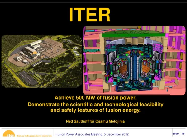
ITER CODAC
ITER CODAC. Bruno Soares Gonçalves bruno@ipfn.ist.utl.pt http://ipfn.ist.utl.pt/EU-PhD/. CODAC. CO ntrol, D ata A ccess and C ommunication system. Large-scale experiments: control and data aquisition challenges. The next generation of physics experiments will be highly complex

ITER CODAC
E N D
Presentation Transcript
ITER CODAC Bruno Soares Gonçalves bruno@ipfn.ist.utl.pt http://ipfn.ist.utl.pt/EU-PhD/
CODAC COntrol, Data Access and Communication system
Large-scale experiments:control and data aquisition challenges The next generation of physics experiments will • be highly complex • raise new challenges in the field of control and automation systems • demand well integrated, interoperable set of tools with a high degree of automation • deliver and process data at a rate of up to hundred GBytes/s. • deploy and integrate systems with different degrees of complexity and provenience
Commercial technology will likely meetthebasic requirements on which physics experiments can leveragefor building future control systems
Future systemsare envisioned to be more thanan order of magnitude larger than those of today However…
ITER hardware developers/providers should be ready to • Providingwell integrated, interoperable set of tools • Deploy and integrate systems with different degrees of complexity and provenience
More challenging will be… providing robust, fault tolerant, reliable, maintainable, secure and operable control systems
Large-scale experiments:R&D on control and data aquisition • R&D activities target • Self-triggered front-end electronics with adequate output bandwidthand data processing • MIMO controllers with efficient resource sharing between control tasks on the same unit • Massive parallel computing capabilities.
Is ITER any different? ITER CODAC is a challenging endeavour • ITER will generate a huge quantity of experimental data • 150 plant systems • 1 000 000 diagnostic channels • 300 000 slow control channels • 5 000 fast control channels • 40 CODAC systems • 5 Gb/s data • 3Pb/year data (e.g. 12 IR cameras in a 10 minutes discharge: 1.728 Tbytes) In addition... ITER will require a far higher level of availabilityandreliabilitythan previous/existing tokamaks .
Why do we need it? • Real Time Measurement and Control of magnetically confined plasmas is a critical issue forsafe operationandhigh performanceof fusion reactors. • It ensures: • Reliability: control the plasma dynamic over long times • Reproducibility: avoid deviations from the reference scenario • Plasma & machine protection: avoid of instabilities & disruptions
Protection to the… environment investment components
What are the functions of the control systems? Fusion machines have awiderange of Plasma Control Systems • plasma control tools: to reach and reproduce scenarios which cannot be programmed • operation supervisor: to protect Plasma and Machine Both thrusts will be steered by the need to satisfy regulatory requirements while effectively controlling a burning plasma.
What are the inherent constraints? • Fusion reactors sites will be a Nuclear Registered sites • Similar to Nuclear power station in terms of quality, audit trails, ..... etc. • Will need control system architecture within the licensing constraints • Requires tools to guarantee safety, protection of investment and guaranteed operation • Hostile environment for measurements, networks, electronics – human access will be restricted • Will require a far higher level of availability and reliability unforeseen on previous/existing tokamaks
Are there similarities with fission reactors? Operation supervisory tools will likely be similar to the ones in use in fission reactors • slow response time of the control system the order of hundreds of milliseconds. • Typical functionality of an industrial SCADA (Supervisory Control And Data Acquisition) • displays on mimic diagrams, • trending, • warning and alarm handling, • manual triggering of commands or changes to set-points. However, fusion reactors are expected to explore more advanced operation scenarios capable of • sustaining for a long duration a steady-state plasma • suppressing plasma instabilities almost completely.
ITER Challenges:Inherent Constraints • ITER is assumed to be totally legacy-free for hardware and software • Methodologies will have to be tested and proved on existing fusion devices before implementation on ITER • It will be necessary to take informed decisions based on technology progress • Maintenance will be an issue and proliferation of technologies must be avoided • ITER is an international project • In-kind procurement world-wide • Integration of Plant Systems from all participants • The implications of in-kind delivery of subsystems need to be recognised • Powerful remote access networks • Remote access security
ITER will generate huge quantities of experimental data – PBytes per year (but still less than LHC) (e.g. 12 IR cameras data resulting from a 10 minutes shot: 1.728 TBytes) ITER will provide tools for continuously accessing and analysing data during a pulse - Requires data indexing by events ITER will have a very strong flexible set of diagnostics and tools for optimising the performance during a pulse - Adequate tools and methodologies need to be developed ITER will have a limited number of pulse cycles and an unlimited number of ideas to be tested – Will schedule and reschedule many activities during a pulse ITER will evolve both equipment and ideas over 20 years – A lifetime of 30 years including procurement – evolution must be built into CODAC ITER Challenges:Scientific Exploitation
What is required for advanced operation scenarios? For fusion burn control is essential to integrate simultaneously • multiple measurements from different sensors, • real-time plasma modelling from several tools • multiple actuators Requires fast control loops with time constraints of the order of tenths of microseconds. Furthermore, the control systems are mandatory to be robust, and fault tolerant
ITER CODAC • CODAC provides the COntrol, Data Access and Communication functions for ITER, allowing integrated operation. • This includes: • continuously monitoring the Plant Systems; • displaying their status to operators including alarms; • preparing and automating scheduled operations (including plasma pulses); • recovering data from Plant Systems; • storing and making all the data available. • CODAC uses multiple logical and physical networks to segregate these disparate functions.
CODAC integrates ALL ITER Plant Systems Many networks: operation, interlocks, safety CODAC functions are like present tokamaks ITER: as seen by CODAC
ITER:Instrumentation and Control • I&C is in 3 clear tiers • Safety: protects personnel, population and environment • Interlock: protects ITER investment • CODAC: operates ITER • I&C is in 2 layers • Plant Systems: local responsibility • Networks when responsibility lies across Plant Systems
CODAC CODAC shall provide: • Supervisory control functions as a project wide and interface specifications between CODAC and Plant Systems. • Central data management functions i.e. data archiving, data monitoring and visualization functions. • PSH functional profile and data exchange software for the asynchronous communication interface between CODAC and Plant System. • Mini CODACas a tool to carry out FAT (Factory Acceptance Test) • Specifications for the Network Interface Units with their interface specifications. • Self-description schema and tool for Plant System I&C designers. • Functional mimic diagrams for Plant System data monitoring, trends, plasma discharge preparation, sequencing, and data display. • Functions for global and plant operating states management, plasma control, data recording with time stamp, data marshalling, data archiving... • Capability to log all commands and state transitions along with all the associated data with time stamping.
Network Interface between plant system I&C and central I&C systems
CODAC and Plant Systems I&C architecture • CODAC Systems • Provides supervisory functionsof ITER plant operation, plasma experiment, overall ITER plant operating status monitoring, data archiving and alarm handling, HMI interface and remote experiment handling functions. • Modular design with Dual Redundancy required
CODAC components • The principal CODAC System is the Supervisory Control System • The Supervisory Control System: • dynamically allocates any required resources to an ITER operation Task. • manages a dynamically evolving set of concurrent activities, each of which is driven by an Operation Schedule. • The Operation Schedule • is prepared by Schedule Preparation and each Operation Schedule requires Schedule Validation before becoming executable. • is executed by Schedule Execution once the resources are made available by SCS. • There is a strong interface between scheduling and ITER operation planning
CODAC components • The status of ITER is obtained from Plant Monitoring, which also generates a data stream for Data Logging. • Maximum refresh frequency proposed is 3 Hz, corresponding to a human reaction. • Minimum rate is 0.1 Hz to ensure a continuous record and continuous functionality checking. • Monitoring data are available in the Experiment Sites to enhance contact with operation. • The functionality is typical of an industrial SCADA (Supervisory Control And Data Acquisition) • displays on mimic diagrams, • trending, • warning and alarm handling, • manual triggering of commands or changes to set-points.
Central data management functions • CODAC shall provide data logging, data monitoring, data archiving and data visualisation functions within the Main Control Room. • Data are generated by different parts of the ITER plant at different sampling rates according to the information itself and according to the operational state of ITER. • The notion of pulse archive also disappears, replaced by the data in a particular pulse being and identifiable time interval in a continuous data retrieval stream. • Storage strategies required for efficient recovery of data taken at different sampling rate (0.1 Hz to 1 MHz). Separating the total data flow into suitable streams to optimize the retrieval of archived information.
CODAC and Plant Systems I&C architecture • CODAC Networks • Provide ITER wide physical and logical interconnections between CODAC and the Plant Systems. • The roles and functions of networks are defined according to their performance requirements.
CODAC Networks • The CODAC architecture is based on distributed systems connected over a set of complementary asynchronous and synchronous networks • Each Plant System and CODAC Systems can communicate over one or more networks • Asynchronous general purpose Plant Operation Network (PON) provides the backbone of CODAC communication for most CODAC data traffic. • General ITER Networks (GIN) used to connect between the Plant Operation Zone and external Experiment and Analysis Sites. • Networks used will depend on the required functionality, volume of data, bandwidth and latency.
High Performance Networks • Some functions of CODAC require deterministic, hard real-time communication and synchronization between distributed nodes. • These requirements are addressed by the CODAC High Performance Networks • Synchronous DataBus Network (SDN) • Time Communication Network (TCN) • Event Distribution Network (EDN) • Audio Video Network (AVN)
Issues:Timing, Synchronization, events and Synchronous data Transport Networks
CODAC and Plant Systems I&C architecture • Plant Systems • provide data acquisition, operation & control, status/alarm monitoring, and data communication functions with the • CODAC systems. • Also have local autonomous operation control independent from the CODAC. • Plant Systems communicates only through CODAC.
CODAC and Plant Systems I&C architecture • Plant System Host • standard image of Plant System to the CODAC. • It is a single point entry for the asynchronous communication with CODAC (data exchange) • Controls data flow, interprets all the commands and passes them to the Subsystem Controller for necessary actions.
Plant System supplier’s responsibility Plant System suppliers shall: • Provide self-description data of their Plant System I&C and shall receive interface requirements from the CODAC. • Provide and implement applications for their Plant System monitoring, data acquisition, autonomous operation and control functions. • Provide Plant System simulators/Plant subsystem simulators. • Carry out Factory Acceptance Tests using mini-CODAC as a testing tool. Also Plant System is responsible to carry out installation, commissioning and SAT at the IO site.
Mini-CODAC Development of a mini-CODAC mandatory • required to test all CODAC concepts prior to full development • provide a development and test tool for Plant System designers Mini-CODAC is a CODAC emulator for development of Plant Systems • Tool for carrying out functional testing of the Plant System to certify Plant System functional integration. • Scalable functionality to achieve limited performance testing of the Plant System interfaces with CODAC. • Used to carry out Provisional Acceptance Tests (and for repeating the FAT if needed) to prove and verify that all plant cabling and connections have been terminated correctly and that the input and output schedule is as required by the design. • Does not define the technical functionality and test processes of Plant Systems but defines and provides environment with limited performance to facilitate integration testing of Plant Systems with CODAC.
Plant System Simulator Used to test the behaviour of Plant Systems during different phases of integration (Factory Acceptance Tests, Commissioning and Site Acceptance Tests and also during plant operation). Plant System/Sub-system simulator should be based on self description data from Individual Plant System/sub-system supplier.
CODAC and Plant Systems I&C architecture • Equipment • May not communicate in a project-wide standardised form. • Configured hierarchically according to the individual Plant System design. • Not procured for direct interface with CODAC but subject to an integration procurement arrangement to deliver as a Plant System component. (sensors, actuators, instrumentation, electronics, modules, racks, cabling, wiring,…)
Sub-systems and equipments 40 LIDAR CONTROL AND DATA ACQUISITION as example Control System Interface Definition • Optics alignment controller interfaces • Laser alignment unit interfaces • Lasers controller interfaces • Detection system controller interfaces • Windows monitoring unit interfaces • Inner wall monitoring unit interfaces • Control and monitoring software specification • Local controller hardware specification Diagnostic systems will have local controllers and data acquisition which may have to be developed to meet the requirements
CODAC components • Plasma Control is implemented as a specific Operation Schedule to maximise reuse of automation and plasma control tools. • General feedback control, including Plasma Control, uses a Synchronous DataBus to communicate data converted to physics units, including an estimate of the error on each signal and its status. • Evaluation of plasma diagnostic information is local in the diagnostic Plant System if this is straightforward. • Information is collected over the Synchronous DataBus for analysing data from multiple Plant Systems and finally transmitted over the Synchronous DataBus to the actuators.
Aim of Control Systems in fusion:JET as an example JET has a wide range of Plasma Control Systems • To reach and reproduce scenarios which cannot be programmed • Quasi-Steady State Experiments • Magnetic and Kinetic Profile & ITB Experiments • Mode Conversion Experiments • Radiation and Impurity Experiments • MHD Experiments • To protect Plasma and Machine • NB Shinethrough (WALLS, PEWS and NBLM) • LHCD Launcher (Monitor Iron and Radiation) • Avoid Disruptions • Mimize waste (Neutrons, Tritium)
Limitations of existing Control Systems: JET as an example • High Maintenance • Proliferation of interfaces • Should converge on modern instrumentation, computer, etc. standards • Lack of commonality and functionality between different devices RTMC systems • e.g. JET PPCC not simply exportable to other devices and vice-versa • Lack of flexibility • Integration of new equipment and physics into the existing infrastructure is time-consuming. • Lack of good transport and integrated models and tools • Integrated development environment and interchange formats • Future developments should acknowledge these issues
How important are the control systems?Vertical Stabilization as example Elongated plasmas are vertically unstable • Loss of control if plasma reaches the vessel protecting tiles. • Dedicated MIMO systems are designed to make the plasma vertically stable so that other controllers can successfully control the plasma position and shape. From F. Sartori, IEEE CONTROL SYSTEMS MAGAZINE, APRIL 2006
Loss of vertical plasma position control in ITER will cause thermal loads on Plasma Facing Components of 30-60 MJ/m2 for ~0.1s. PFCs cannot be designed to sustain such (repetitive) thermal loads Vertical Displacement Events also generates the highest electromagnetic loads A phenomenological extrapolation of horizontal forces from worst JET cases implies horizontal loads ~45MN on ITER vacuum vessel. MHD wetted kink model developed to simulate the horizontal loads predicts ~20MN Vertical loads ~90MN Plasma vertical position in ITER must be robust & reliableto ensure a vertical plasma position control loss is a very unlikely event How important are control systems?ITER Vertical Position Control