Experimental Study of Pile Foundations during Liquefaction-Induced Lateral Spreading
This project involves an experimental and micromechanical computational study of pile foundations under liquefaction-induced lateral spreading. The study includes tasks like conducting 1g tests on pile foundations to understand their behavior. The project aims to analyze the response of pile foundations to lateral spreading and liquefaction in detail. It includes testing single pile and group pile configurations to simulate real-world scenarios. The research also involves data collection on soil properties, ground motions, and instrumentation setup. This comprehensive study is crucial for improving the understanding of how pile foundations respond to seismic events involving liquefaction-induced lateral spreading.

Experimental Study of Pile Foundations during Liquefaction-Induced Lateral Spreading
E N D
Presentation Transcript
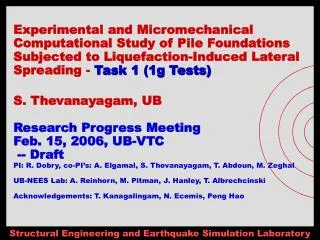
Experimental and Micromechanical Computational Study of Pile Foundations Subjected to Liquefaction-Induced Lateral Spreading - Task 1 (1g Tests)S. Thevanayagam, UBResearch Progress MeetingFeb. 15, 2006, UB-VTC -- DraftPI: R. Dobry, co-PI’s: A. Elgamal, S. Thevanayagam, T. Abdoun, M. ZeghalUB-NEES Lab: A. Reinhorn, M. Pitman, J. Hanley, T. Albrechcinski Acknowledgements: T. Kanagalingam, N. Ecemis, Peng Hao
Pile (Test 1A: High EI pile, Test 1B: Low EI pile) F#55 Sand, Dr~45% 2-D Laminar Box (24 Laminates) 6.2 m Ball Bearings Shaking Frame on Strong Floor a=2 or 3 deg. SECTIONAL VIEW 3.35 m 2.75 m 5.0 m 5.6 m PLAN Tests 1 and 2: Single Pile(shaking in perpendicular directions) • Yr-1: Tests #1A & 1B • Yr-2: Tests #2A & 2B
Pile Cap Pile F#55 Sand, Dr~45% 2-D Laminar Box (24 Laminates) 6.2 m Ball Bearings Shaking Frame on Strong Floor a=2 or 3 deg. SECTIONAL VIEW 3.35 m 2.75 m 5.0 m 5.6 m PLAN Tests 3 and 4: Group Pile(shaking in perpendicular directions) • Yr-2: Tests #3 • Yr-3: Test #4
Planning, Design, Fabrication & Instr. Procurement • Box, Sand, Control, Ground Motion, Instruments • Preparatory Testing • Sand Construction, Dry Runs & Preliminary Equipment Tests • Saturated Free-Field Liquefaction • Level Ground (LG-1)– Harmonic progressive amplitude increase (May-June 06) • Sloping Ground (SG-1)- Harmonic progressive amplitude increase (June-July 06) • Pre-test Data for FEM/DEM modelers– 2mo before tests for Class A prediction • Single Pile • High-EI Pile (Test 1A)– Harmonic progressive amplitude increase, 0.2-0.3g (Aug. 06) • Low-EI Pile (Test 1B)– Harmonic progressive amplitude increase, 0.2-0.3g(Oct. 06) • Coordination w/ Centrifuge Tests & IT Year-1 Plans (2005-06)
Parameter Unit Value Single laminate thickness m 0.254 Single laminate weight kN 7 Empty box weight excluding steel bridge kN 168 Empty box weight including steel bridge kN 250 Friction between laminates % ----- Inter-laminate displacement limit m 0.036 Maximum soil volume m3 77.2 Maximum weight (soil & box) kN 1850 Maximum horizontal acceleration g 0.3 Laminar Box Dimensions
Laminar Box – Strong Floor Foot Print Strong Floor – Reserved April 1 – Oct.31, 06
LAMINAR BOX-ACTUATOR Reserved April 1 – Oct.31, 06 Controller – To be tested by Mark Pitman – 3/15-4/15/06
Loading Frame Design Completed; Quotes Accepted; Purchase in progress; Delivery March15, 06
Laminar Box – Strong Floor Modification Machined Base Steel Plate – UB NEES Funded PLAN VIEW
Floor Reactions (kips) (Dead Weight) Design Completed; Loading within Tolerable Limits; Strong Floor to be leveled using Steel Base Plate, Funding approved; Purchase in progress
Floor Reactions (kips) (Longitudinal Shaking) • See Next Page for results after removing tensions
Floor Reactions (kips) (Longitudinal Shaking) • All negative reaction Supports are removed
LG-1 & SG-1 Data for FEM/DEM Modelers • Draft Report Released Feb 15, 06. • Ground Motion Report – Released Feb. 1, 06. • Soils Report -- Thevanayagam, S., Shenthan, T., and Kanagalingam, T., (2003). “Role of intergranular contacts on mechanisms causing liquefaction and slope failures in silty sands. “Final Report, USGS Award No. 01HQGR0032 and 99HQGR0021; US Geological Survey, Department of Interior, USA,‘http://erp-web.er.usgs.gov/reports/abstract/2001/pt/01hqgr0032-report.pdf , 396p. • Soil Property Test Data – Available in EXCEL Format
Draft Ground Motion:umax = 0.74’’f = 2 Hzfn = 5 – 7 Hzamax = 0.3 g
Expected Pore Pressure Vs Time - Draft Shaking Motion ru vs Time (Based on UB Energy based Liq. Model)
Equipment & Instruments – Plan Planning & Quotes Completed; Purchase in progress; Delivery April 5, 06
Instrumentation – LG-1 & SG-1 Plan View Instrumentation to be coordinated with NEES-Wood Project
Instrumentation – Test 1A & 1B N-S W-E MEMS Shape Cable
KRYPTON Soil-Pile Instrumentation
Pile Cap Pile F#55 Sand, Dr~45% 2-D Laminar Box (24 Laminates) 6.2 m Ball Bearings Shaking Frame on Strong Floor a=2 or 3 deg. SECTIONAL VIEW 3.35 m 2.75 m 5.0 m 5.6 m PLAN Group Pile - Test 3 (Yr-2)
Planning, Design, Fabrication & Procurement • Box, Sand, Instruments - Design completed, Quotations received, purchase order in progress – Product Delivery March 15. Instruments Delivery April 15. • Box Assembly – Scheduled March 15 – 31 • Ground Motion to be discussed - Finalize by April 15 • Control – Mark Pitman - Scheduled March 1-April 15 • Preparatory Testing • Sand Construction, Dry Runs & Preliminary Equipment Tests – Scheduled April 1-30 • Saturated Free-Field Liquefaction • Level Ground (LG-1) – Scheduled May 1-30 • Sloping Ground (SG-1) – Scheduled June 1-30 • Pre-test Data for FEM/DEM modelers – Preliminary Report Released Feb. 15 • Single Pile • High-EI Pile (Test 1A) – Preparation May 1-July31; Testing Aug 1-31 • Low-EI Pile (Test 1B) – Preparation May 1-July31; Testing Sept. 1-30 • Coordination w/ Centrifuge Tests & IT Year-1 Status
Equipment & Instruments – Plan Planning & Quotes Completed; Purchase in progress; Delivery April 5, 06
Sand Construction - Hydraulic Filling Initial Slurry Pump Tests completed – Oct 05; Sand pumping/Density Control Tests – April 06 (weather)
Field Hydraulic Fill Placement Methods & CPT Results Low Speed + Compaction High Speed Bottom Dump
Hydraulic Fill – Field CPT Data(Mitchell et al.) Better Control Possible in the Lab. Environment; Includes plans for development of placement controls to achieve desired density ranges