FIBER OPTIC STRAIN SENSORS
540 likes | 1.4k Vues
FIBER OPTIC STRAIN SENSORS. Beril Bicer. University of Illinois at Urbana-Champaign. Content. Optical Fiber Fiber Optic Sensors Measured Parameters Main Advantages Basic Components of FOS Setup Applications Classification of FOS Fiber Optic Strain Gages Products. Optical Fiber.

FIBER OPTIC STRAIN SENSORS
E N D
Presentation Transcript
FIBER OPTIC STRAIN SENSORS Beril Bicer University of Illinois at Urbana-Champaign
Content • Optical Fiber • Fiber Optic Sensors • Measured Parameters • Main Advantages • Basic Components of FOS Setup • Applications • Classification of FOS • Fiber Optic Strain Gages • Products
Optical Fiber • a filament of transparent dielectric material, glass or plastic • usually cylindrical in shape • a guidance system for light Optical fiber is :
J1 n1 n2 J2 Optical Fiber SNELL’S LAW: n1 sin J = n2 sin J where n is refractive index • Guidance is achieved through multiple reflections at the fiber walls. • Core, transparent dielectric material, surrounded by another dielectric material with a lower refractive index called cladding. (n1 >n2) • In practice, there is a third protective layer called jacket.
Ray Transmission through an Optical Fiber Critical angle of reflection (sin Jc= n2 /n1)
Fiber Optic Sensors Basic Components: • source of light • a length of sensing • (and transmission) fiber • a photo-detector • demodulator • processing and display optics • required electronics
Measured Parameters • Light intensity • displacement (position) • pressure • temperature • strain (rotation and displacement) • flow • magnetic and electrical fields • chemical compositions • velocity, acceleration and vibration • force and stress
Non-electric (immune to electromagnetic and radio-frequency interference) withstand high temperature and harsh environments (corrosion) High shock survivability (explosion or extreme vibration) high accuracy and sensitivity light weight and small size high capacity and signal purity multiplexing capacity Can be easily interfaced with data communication systems Main Advantages
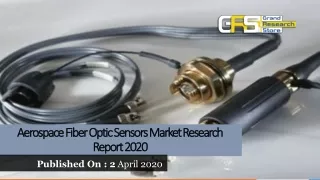
Applications • Real-time monitoring of civil engineering structures. • Structural monitoring of aircraft, both in-flight and on-ground • Instrumentation of robots used on board in the International • Space Station • Testing and analysis of solid rocket motors • Smart structures instrumentation • Fiber Aerospace guidance and control • Industrial control • Damage localization in civil, mechanical, and aerospace • structures • Embedment in concrete structures
Classification of FOS • A. Based on application areas: • physical sensors (measurement of temperature, stress, etc) • chemical sensors (measurement of pH content, gas analysis, spectroscopic studies, etc.) • biomedical sensors (measurement of blood flow , glucose content, etc.)
Classification of FOS B. Based on modulation and demodulation process: • phase-modulated sensors • compare the phase of light in a sensing fiber to a reference fiber in a device called interferometer. • Light is not required to exit the fiber at the sensor (no optical loss) • more complex in design • better sensitivity and resolution
Classification of FOS Example: Mach-Zehnder Interferometric sensor
Classification of FOS B. Based on modulation and demodulation process: • intensity-modulated sensors • Light is required to exit the fiber at the sensor (optical loss) • simpler in design • more economical • widespread in application
Classification of FOS B. Based on modulation and demodulation process: • spectrally-modulated sensors • measures the changes in the wavelength of the light due to the environmental effects.
Classification of FOS C. Based on sensing characteristics of fibers • extrinsic sensors • a coating or a device at the fiber tip performs the measurement.
Classification of FOS C. Based on sensing characteristics of fibers • intrinsic sensors • fiber itself performs the measurement.
Fiber Optic Strain Sensors • A. Intensity Modulated Strain Gages • Reflective sensors • One bundle is used to transmit the light to a reflecting target • Other collects the reflected light and transmits to a detector • Any movement of the target will effect the intensity of the reflected light.
Fiber Optic Strain Sensors • Plain reflective displacement sensors have a limited dynamic range of about 0.2 in. • Can be improved by a lens system to 5 in. • sensitive to the orientation and contamination of the reflective surface
Fiber Optic Strain Sensors • A. Intensity Modulated Strain Gages • Micro-bend Sensors • If a fiber is bent, a portion of the trapped light is lost through the wall.
Fiber Optic Strain Sensors • B. Phase Modulated Strain Gages • Fabry-Perot Interferometers (FPI) • light source is conveyed via an optical fiber to two mirrors (reflectors). • When the displacement between the mirrors has changed due to strain, optical spectrum changes • absolute distance between the mirrors gives the strain.
Fiber Optic Strain Sensors • Extremely sensitive • provides point-sensing capability • excellent mechanical properties • output is easy to process • difficult to make rugged enough for harsh construction env. (embedding in concrete)
Product: EFO Embedded Strain GageFISO Technologies • 70 mm long sensor • can be embedded in concrete • intrinsic Fabry-Perot strain gage is bonded in a very small hole in the center of the steel body. • can be cast directly into the wet mix • can be encapsulated into a concrete briquette, then cast into wet concrete • can be placed into a pre-drilled hole and grouted. • Diameters are 3mm and 30 mm. • range, +/- 1000, 1500micro strain • resolution <0.01% full scale • Temperature range, -55 oC to 85oC
Product: Embeddable EFPI Strain GageLuna Innovations Inc. • 2-10 mm length, 350 micrometer outer diameter • sensitivity, +/- 5000 micro strain • resolution <1 • Temperature range, -100 oC to 350oC • accuracy, 1% • Measurement cycle, 100kHz
Product:Wide Sensing Fiber Optic CableSunX-Ramco Inc. • 11 mm wide sensing area • long sensing distance • freely cuttable fiber cable • 2 m. lenght