Download
1 / 33
330 likes | 461 Vues
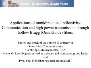
Photos and much of the content is courtesy of OmniGuide Communications Cambridge, Massachusetts, USA (where M. Skorobogatiy served as a theory and simulation group leader) and Prof. Yoel Fink fiber research group at MIT. Quasi - 1D systems, Bragg fibers.

E N D
Photos and much of the content is courtesy of OmniGuide Communications Cambridge, Massachusetts, USA (where M. Skorobogatiy served as a theory and simulation group leader) and Prof. Yoel Fink fiber research group at MIT Quasi - 1D systems, Bragg fibers Applications of omnidirectional reflectivity.Communication and high power transmission through hollow Bragg (OmniGuide) fibers.
Core Cladding Hollow core Mirror Cladding The problem: making the perfect mirror Conventional Dielectric Mirror Angular dependent reflectivity with very low optical loss Conventional Hollow Metallic Metallic Mirror Omnidirectional reflectivity with optical loss Hollow Core Cladding Omnidirectional Mirror Reflects all angles with very low loss OmniGuide
High-Energy Laser Guidance in the IR Laser Surgery, Materials Processing Few applications of hollow Photonic Bandgap fibers Low loss transmission of IR signals Communications IR Imaging Fiber Devices Dispersion Compensating fibers, Tunable Cavities, Lasers, Nonlinear Devices
OmniGuide/MIT hollow core fiber B. Temelkuran et al., Nature 420, 650 (2002) + OmniGuide Communications Output of a straight 25cm piece of fiber, l=10.6mm
Step 1: Stoichiometric thermal evaporation of As2Se3 onto free-standing PES film Step 2: Rolling of coated film into cladded hollow multilayer cylinder on SiO2 tube substrate Step 3: Vacuum thermal consolidation Step 4: Etching and removal of SiO2 Spiral OmniGuide Preform Processing Courtecy of OmniGuide Communications
Step 2 Step 4 Step 3 Step 1 Evaporation Fiber Drawing Structured Preform Fabrication Materials Synthesis The OmniGuide Fabrication Sequence Courtecy of OmniGuide Communications
Preform-Based Fabrication Strategy Courtecy of OmniGuide Communications Preform Partially Drawn Preform Mirror (SEM Image) 1 in 3-30 meter draw tower 5 µm
Bragg fiber by stacking technique Silica-Air, Bragg Like fiber G. Vienne, et al. “First demonstration of air-silica Bragg fiber,” OFC, PDP25, 2003
Reflection form the planar dielectric mirror, modes of hollow metallic waveguide and hollow Bragg fiber Frequency regions (gray) of omnidirectional reflection form the multilayer reflector stack Modes of hollow metallic waveguide = Modes of hollow Bragg fiber AND "Analysis of mode structure in hollow dielectric waveguide fibers,“ M. Ibanescu, S.G. Johnson, M. Soljacic, J. D. Joannopoulos, Y. Fink, O. Weisberg, T.D. Engeness, S.A. Jacobs, and M. Skorobogatiy, Physical Review E, vol. 67, p. 46608, 2003
Wavelength scalability. Different draw conditions shift the transmission spectrum Courtecy of Y. Fink (MIT) OmniGuide FTIR spectrum Index contrast nh/nl~2.5/1.7; Rcore~200mm; Fundamental bandgap at l=3mm Wavevector
Colorful fibers Fibers of different draw down ratio exhibiting continuously changing position of a higher order band gap Y. Fink et al., Advanced Materials 15, 2053 (2003) Fiber Outer Diameter decreases
Modes of OmniGuide hollow core fiber Most compatible with Gaussian laser source and high power Ultra low loss, hard to couple to Gaussian laser source • Leaky modes of a Bragg fiber are calculated using transfer matrix method • Absorption losses and nonlinearities of the underlying imperfect materials are greatly suppressed as most of the field is concentrated in the hollow core
Modal radiation and absorption losses Index contrast nh/nl~4.6/1.6, Rcore~15mm, bulk material loss 1dB/m, 12 mirror periods "Low-loss asymptotically single-mode propagation in large-core OmniGuide fibers,“ S.G. Johnson, M. Ibanescu, M. Skorobogatiy, O. Weisberg, T.D.Engeness, M. Soljacic, S. Jacobs, J. D. Joannopoulos and Y. Fink, Optics Express, vol. 9, pp. 748-779, 2001
HE11 High power guiding applications Input Input Transmission Coupling to HE11, higher order and cladding modes Beam degradation due to inter-modal scattering HE11 Rcore~100-500mm Region of increased heating Region of increased heating Beam quality M2 degradation due to higher order mode content Radiation, absorption loss ~ 1/R3core Bending loss ~ Racore/Rbend Modeling tools • Beam quality M2 estimation via free space propagation • Coupling efficiency at the fiber input • Temperature rise due to imperfect coupling • Design and optimization • Scattering/radiation due to • imperfections/bends • Excess heating due to bends M. Skorobogatiy, S.A. Jacobs, S.G. Johnson, O. Weiseberg, T.D. Engeness, Y. Fink, “Power Capacity of Hollow Bragg Fibers, CW and Pulsed Sources,” TuA4.6, Digest of the LEOS Summer Topical Meetings, pp. 66-67 (2003)
Components for high power guiding applications Courtecy of OmniGuide Communications
OmniGuide fiber, l=10.6mm Incoming Gaussian, m=1 mode Rc~300mm ~80%-90% HE11 mode Dry air cooling Metal tube coupler Imperfect coupling and heating (theory) Amplitudes of excited modes are calculated by matching transverse electric and magnetic fields of the incoming Gaussian in free space and eigen fields of the fiber/coupler, for an unoptimized coupler power in the lowest loss m=1 mode HE11 is 80%-90%
Imperfect coupling and heating (theory) • Temperature rise (red) along the fiber length due to imperfect coupling (80% in HE11 and 20% in parasitic modes) – full solution. In green, temperature distribution if 100% HE11 mode is excited. In blue, temperature distribution ignoring the interference effects between the modes. • Heat flow equation is solved with heat sources defined by amplitudes of excited parasitic modes due to imperfect coupling
Imperfect coupling and heating (experiment) Courtecy of OmniGuide Communications Non-uniform temperature rise in a fiber under imperfect coupling MAX Laser and coupler Temperature Fiber MIN
m m Wavelength ( Wavelength ( m) m) 1.67 1.67 2.0 2.0 2.5 2.5 3.33 3.33 5.0 5.0 4.0 4.0 3.0 3.0 Transmission (arb. u.) Transmission (arb. u.) 2.0 2.0 1.0 1.0 0.0 0.0 7000 7000 6000 6000 5000 5000 4000 4000 3000 3000 2000 2000 -1 -1 Wavenumber (cm Wavenumber (cm ) ) Bending loss in OmniGuide fiber (experiment) Bend loss ~ 3 dB through full “knot” of 1 cm radius B. Temelkuran et al., Nature 420, 650 (2002)
Bends and beam degradation (experiment) Courtecy of Y. Fink (MIT) Bent – 360O, 10 cm radius Straight – 25 cm long
Rcooler Rcore Rbend=20cm Bends and heating (theory) • Temperature distribution in a fiber bend • Amplitudes of excited modes in a bend are found by propagating HE11 incoming field through bend by Coupled Mode Theory • Heat flow equation is solved with heat sources defined by amplitudes of excited modes
Transmission window and loss Courtecy of Y. Fink (MIT) 10.6 mm Ability to control location of transmission window for specific applications
Input Gaussian → HE11direct launch Moderate loss HE11 mode (~10dB/km) Gaussian → TE01 mode converter Ultra low loss TE01 mode (~0.1dB/km), incompatible with Gaussian Telecommunications applications TE01 HE11 Rcore~15mm HE11 radiation, absorption loss ~ 1/Rcore TE01 radiation, absorption loss ~ 1/R3core, non-linearities ~ 1/R7core Bending loss ~ 1/R2bend-1/Rbend Modeling tools • Coupling of the laser source to the fiber HE11 or TE01 modes • Mode converter design • Modal losses due to • absorption/radiation • micro and macrobends • fiber imperfections • Dispersion management • Signal degradation due to • nonlinearities • micro and macro bends • fiber imperfections • Polarization Mode Dispersion
HE11 [2pc/a] Zero dispersion Very high dispersion Low dispersion [2p/a] Highly designable group velocity dispersion of OmniGuide modes
TE01is a non-degenerate mode, and thus cannot be split PMD is zero Polarization-mode dispersion (PMD) of a doubly degenerate HE11mode: …pulse spreading! same group velocities: different group velocities: stochastic stress, imperfections… “single-mode” fiber PMD of the TE01 and HE11 modes HE11: TE01:
Challenges: coupling to Bragg fibers. HE11 →TE01 ”serpentine” mode converter (theory) Amplitude of fiber wiggling d=49nm, N=35 turns, Dw=512mm • SMF-28 silica fiber at 630nm, • Rc=4.1mm, Dn/nc=0.36%, 7 guided modes: • LP01 - HE11 • LP11 - TE01,TM01,HE21 • LP21 - EH11, HE31 • LP02 - HE12
HE11 → TE01 ”serpentine” mode converter (experiment) Courtecy of OmniGuide Communications 33% LP01, 65% LP11, 2% LP21+LP02 99.8% LP01 TE01 HE11 M. Skorobogatiy, C. Anastassiou, S.G. Johnson, O. Weiseberg, T.D. Engeness, S.A. Jacobs and Y. Fink, “Quantitative characterization of higher-order mode converters in weakly multimoded fibers,” Optics Express 11, 2838 (2003)
Bragg fiber components and systems Device applications and functional fibers
Inter-Fiber Interaction 2) Stacked fiber Two closely spaced fiber cores are provisioned on the preform level. Directional coupler is then drawn from such a preform. Core 1 Core 2 Drawing 2) Bragg fiber Individual fibers are drawn. Outer polymer cladding can be removed by dissolving the polymer. B.J. Mangan, J.C. Knight, T.A. Birks, P.S. Russell, A.H. Greenaway, Electron. Lett. 36, 1358 (2000). Fiber alignment Cladding removal
Two related problems of directional coupling • Cabling of several photonic band gap fibers • parasitic coupling between waveguides due to the radiation leakage outside of the fiber core M. Skorobogatiy,"Hollow Bragg fiber bundles: when coupling helps and when it hurts,” OPTICS LETTERS 29, 1479 (2004) 2) Fiber components (directional couplers) Coupling has to be strong enough so that power transfer from one waveguide to another happens on a length scale much smaller than modal decay length (radiation loss) Coupling through radiation field resonance in the inter-fiber region M. Skorobogatiy, K. Saitoh and M. Koshiba, "Resonant directional coupling of hollow Bragg fibers,” OPTICS LETTERS 29, 2112 (2004)
Functional Bragg fibers By creating a “thick” layer in the reflector, fiber transmission can be suppressed in the middle of a band gap. Application of stress offers tuning by changing defect wavelength of a resonator. Y. Fink et al., Advanced Materials 15, 2053 (2003)
Tin “wires” Bragg reflector Functional Bragg fibers Optical fibers can be integrated during drawing with “non-trivial” components such as electric wires, semiconductor devices, etc. Y. Fink et al., Nature 431, 826 (2004)
Functional Bragg fibers Optical fibers can be integrated during drawing with “non-trivial” components such as electric wires, semiconductor devices, etc. Bragg reflector Tin “wire” Semiconductor glass Y. Fink et al., Nature 431, 826 (2004)