Download
1 / 34
370 likes | 634 Vues
Liquid Crystals: Properties and technology. Dr. M. Manickam School of Chemistry The University of Birmingham M.Manickam@bham.ac.uk. CHM3T1 Lecture- 8. Out line of This Lecture. Introduction Properties of liquid crystals Different types liquid crystal displays

E N D
Liquid Crystals: Properties and technology Dr. M. Manickam School of Chemistry The University of Birmingham M.Manickam@bham.ac.uk CHM3T1 Lecture- 8
Out line of This Lecture • Introduction • Properties of liquid crystals • Different types liquid crystal displays • Fabrication and operation of liquid crystal displays • Final comments
Learning Objectives • After completing this lecture you should have an understanding of, and be • able to demonstrate, the following terms, ideas and methods. • Understand how the liquid crystals interact with surfaces • 2. Understand how the liquid crystals interact with light • 3. Understand how the liquid crystals interact with electric fields • 4. How do liquid crystals displays work? • 5. How the Twisted Nematic Liquid Crystal Display work (TNLCDs)? • 6. How the Super Twisted Nematic Crystal Display Work (STNLCDs)? • 7. The difference between TN and STN Devices • 8. How the Surface-Stabilised Ferroelectric Liquid Crystal Display Work • (SSFLCD)?
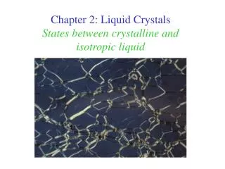
Anisotropic Liquid An anisotropic liquid is a liquid, i.e. it has fluidity in much the same way as solvent such as water or chloroform has. However, unlike water or chloroform where there is no structural ordering of the molecules in the liquid, molecules in anisotropic liquid are on average structural order relative to each other along their molecular axis.
Anisotropy Moving plate Moving plate Moving plate c: Fixed plate b: Fixed plate a: Fixed plate Figure- 1 Diagram to represent a method of demonstrating in a liquid crystal a; Director is pointing out of the page b; Director is in the direction of the moving plate c; Director points up or down
Anisotropy An isotropic material is one whose properties do not change with direction. Both liquids and gases are isotropic. However, liquid crystals and some solid e.g. quartz, are anisotropic. Liquid crystals anisotropy is related to the alignment of their molecules relative to each other. A good way of illustrating this is to consider the action of sliding two flat plates over one another after liquid crystals have been placed in between them (Figure1) The force necessary to move the top plate over the fixed plate is approximately the same for cases (a) and (b) but is much higher for (c)
Alignment at Surfaces Figure -2: Schematic to show a single alignment layer of liquid crystal molecules b; perpendicular to a surface Heterotopical alignment a; parallel to a surface Homotropical alignment
Alignment at Surfaces The inherent tendency for liquid crystals to align is so sensitive that they can readily be made to align with any surface. Various methods of treating a glass surface can be used. For example, by simply rubbing it in one direction with a piece of cloth or preparing it with a surfactant, it is possible, to induce alignment of the director at almost any angle to the surface. Most important cases are when the alignment is parallel (Figure-2a) and perpendicular (Figure- 2b) to the surface of the glass. Figure- 2 shows the alignment of a single layer of liquid crystal molecules, this will in turn align the molecules in the layer above for several micrometers. This alignment is made use of in the technological applications of liquid crystals, in particular parallel alignment is of importance in the twisted nematic display which will be discussed latter.
Permanent Electric Dipole Many liquid crystals molecules are composed of neutral atoms and not charged. However, it is possible for the bonding between the atoms of a molecule to be such that a permanent electric dipole is produced. The result is that the molecule bears a positive charge at one end and a negative charge at the other. One example is a common calamitic liquid crystals template, the alkoxycyanobiphenyls (Figure-3). Resonance structure of an alkoxycyanobiphenyl, producing a permanent electric dipole Figure-3
Interaction with Electric Fields If no electric field is present, the permanent electric dipole on the liquid crystal molecules are not aligned, although the molecules themselves are aligned with respect to one another. When direct current is applied the molecule will orient themselves along the field (Figure-4). This property is unique to liquid crystals, in a liquid the fast, disordered motion of the molecules prevents the same orientation from occurring, and in solids, the bonding between molecules means they are unable to change their positions. The principle features of liquid crystals enabling this interaction with electric fields are their freedom of movement, like isotropic liquids, and their maintenance of orientation order, like crystalline solids. Figure-4 Diagram to illustrate the effect of an applied electric field on the alignment of liquid crystal molecules. applying an electric field
Interaction with Light Unpolarised light can be considered as being made up of electromagnetic waves oscillating in different planes. A polariser can be placed in front of an unpolarised light source, this allows waves in only one plane through and polarises the light. The plan-polarised light can then be completely blocked by a second polariser fixed at right angles (i.e. crossed) to the first as shown in Figure-5 Figure- 5: Demonstration of the action of polarisers on unpolariserd light Light source Polariser 1 Polariser 2
Polariser and Analyser Figure : (a) When the polariser and analyser are in a parallel set up, their optical axes allow light transmission; (b) when the polariser and analyser are crossed, the light from the polariser is absorbed by the analyser, resulting in dark condition.
Birefringence Anisotropic materials produce different values for the index of refraction when the light is linearly polarised along the x-axis and when it is polarised along the y-axis. This phenomenon is referred to as birefringence. Due to the aligning abilities of liquid crystal molecules, it is possible to illustrate their birefringence in a different manner (Figure- 6). Different indices of refraction are produced when the liquid crystal molecules in a sample are aligned at different angle relative to the incoming plane-polarised light. It is birefringence that is responsible for the vivid colours observed in LCs when viewed under an OPM X-polarised light Perpendicular to x-polarised light n1= c/v1 c v1 The back lines represent the alignment layers of the LCs molecules X-polarised light Parallel to x-polarised light n1= c/v1 v1 c Figure-6: Diagram to show effect of liquid crystals aligned
Helical Pitch The pitch is the distance for one full director rotation If the molecules that form a liquid crystals phase are chiral (lack of inversion symmetry), then chiral phases exist in place of certain non-chiral phases. In calamitic liquid crystals, the nematic phase is replaced by the chiral nematic phase, in which the director rotates in helical fashion about an axis perpendicular to the director. The pitch of a nematic phase is the distance along the helix over which the director rotates by 360o The structure of the chiral nematic phase. The views represent imaginary slices through the structure and do not imply any type of layered structure Chiral Nematic Phase
LCs Displays LCs have diverse applications, they are chiefly known for their extensive exploitation in display application. Liquid crystalline materials are used extensively in electro-optic (EO) devices due to their anisotropic properties (mainly alignment in electric field and birefringence) combined with the processability of the fluid state. Therefore, LCs have been used in displays for more than thirty years starting with the simple passive-matrix displays to the technologically advanced multiplex active-matrix displays.
Fabrication of LCDs Whatever type of liquid crystal display (LCD), Figure- 7 illustrates the elements that are generally present. The central unit is constituted by the LC film, sandwiched between lamellae of functional elements as shown in Figure- and listed in Table-1 Figure-7: Scheme of the sequence of the most common parts used for the fabrication of LCDs
Main Layers in LCDs Table- 1. Main layers applied in LCDs. The first layer is the one adjacent to the glass sheets and the last one is in direct contact with the inner LC film The quality of any LCD depends strongly upon the physical properties of the LC. To achieve a high standard of performance it is essential to select the most appropriate LC material according to the specific requirements of the desired type of display.
Physical properties of calamiticmaterials for displays Consequently, in general LCs must satisfy characteristics such as the following: • Liquid crystalline at room temperature and over the entire temperature range of the display operation, • Chemically, electrochemically and photochemically stable, • High resistivity, • Low rotational viscosity, • Either low or high birefringence, depending upon the type of display, • Permanent electric dipole, hence either a positive or negative dielectric anisotropy • However, it is impossible that these demands are satisfied by a single liquid crystalline species alone. Therefore, formulations of LC mixtures are usually employed in LCDs.
Twisted Nematic Displays (TNDs) TNDs was invented by Schadt and Hefrich, and represented the first successful application of LCs. Together with the super twisted nematic displays (STNDs), the TNDs still dominate the entire commercial production of displays. The principle of the operation of these devices is based on the optical absorption or variable birefringence effects of nematic LCs, subjected to a switching electric field.
Operation Principles of Twisted Nematic Displays The nematic materials used in these devices are characterised by a positive dielectric anisotropy, as a consequence of the presence of highly polar terminal groups, resulting in the molecular dipole being oriented along the molecular director and the long axis (Figure-8). permanent dipole No permanent dipole Figure-8: N-(4-ethoxybenzylidene)-4’-aminobenzonitrile is a typical example of one of the first nematic liquid crystal used in TNDs, with positive dielectric anisotropy.
Operation Principles of TNDs [off-state] In these displays, the LC is positioned between two glass plates with parallel (homogeneous) alignment of its molecular director with the glass walls. However, the two glass plates twisted by 900 relative to each other (Figure- 9a) In such a geometry the LC is forced to perform a 900 twist of the director from plate to plate, resulting in a helical structure, whose chirality is controlled by additional doping (~ 1%) with a chiral nematic material. The distance between the plates, hence the thickness of the LC film, is typically 6-10µm, which corresponds to half of the helical pitch. To complete the TND unit, a pair of crossed (900) polarisers is placed on the outer side of the glass plates. In the absence of an external electric field, when linearly polarised light enters the device, the LC film acts as an optical wave guide rotating the polarisation of the light by 900. Thus, the light reaches the second polariser with its polarisation plane parallel to the polariser axis and is transmitted. In this configuration the display appears bright (off-state) (Figure -9a)
Operation Principles of TNDs [ on-state] However, when an electric field (~ 2 V µm -1) is applied (on-state), the LC molecules reorient in order to align the molecular director with the external electric field, causing the helical arrangement to be unwound. As a consequence, the light passing through the LC film, is not guided through 900, and is not able to pass through the second polariser(Figure- 9b). Upon removal of the electric field the LC molecules will relax back into the initial twisted state, in a time dependant manner determined by the rotational viscosity parameter. In some displays, placing the polarisers parallel rather than perpendicular to each other reverses the off- and on- state.
Operation Principle of Supertwisted Nematic Displays (STNDs) In the TNDs the switching speeds are of the order of milliseconds, which is fast enough for watches, calculators, and similar low information content application. However, for more sophisticated real-time devices, where the higher data transfer rates demand faster response time than tens of milliseconds, they are not suitable. STNDs represent an improvement relative to the TNDs, and in fact this type is the one used in more sophisticated applications such as video cameras, monitors, and laptops displays. The fabrication characteristic of the STNDs requires the LC material to perform a rotation up to 2700. This extra rotation allows the STNDs to have a steeper voltage-brightness response curve (Figure- 10), and additionally widens the viewing angle, achieving a higher contrast. The overall result is a higher performance type of display relative to the TND
Supertwisted Nematic Displays (STNDs) Figure-10 Response curve of a STND (`- ) compared with the response of an ordinary TND (----). The steeper response exhibited by the STND makes a wider range of brightness possible.
Display Construction In order to utilise the anisotropic properties of LCs in an electrooptic device, it is necessary to provide means whereby different regions of an LC layer will show different optical properties
Final Comments Clearly the most important applications of liquid crystals will remain in the area of displays for the near future. We can expect that the next generation of LCDs will be brighter and faster, finding their way into new applications such as flat panel televisions, electronic newspapers, and high intensity projection systems. It might not be too far in the future that optical computing becomes commonplace, and it will be interesting to see what role LCSLMs play in this new technology. Likewise, polymer liquid crystals may find uses in displays as well, putting their unique structural properties to good use. While it is impossible to predict the future, liquid crystal technology over the last quarter century has demonstrated an ability to sustain progress in two important arenas, increased device performance and reduced product cost. If these qualities continue, the future of liquid crystals will remain bright for years to come.
Further Reading • Depp, S. W. and Howard, W. E. (1993) Flat Panel Displays. Scientific American, Vol. 268, 90-97, March. • Mosley, A. (1993) Liquid Crystal Displays: An Overview. Displays, 14, April. • Schadt, M. (1989) The History of Liquid Crystal Display and Liquid Crystal Material technology. Liquid Crystals, Vol. 5, 57-71
Operation Principles of TNDs Figure- 9: Schematic representation of the (a) off- (bright) and (b) on-state (dark) geometry of a TND. The polariser and analyser, which are arranged parallel to the LC director orientation at the adjacent glass plates, are oriented at 900 (cross) to each other
Surface-Stabilised Ferroelectric Liquid Crystal Display (SSFLCDs) Ferroelectric LCs (FLCs) show a fast ( ~100 µs or less) switching rate between two equally stable polarised states (P1 and P2) (Figure-11), driven by the application of a reversible electric field. The bistability of the FLC molecules to remain in either of the two opposite polarised states, represents the basic principle for the development of ferroelectric liquid crystal displays (FLCDs). To date the FLCDs, which has been developed is the so-called surface –stablised ferrolectric liquid crystal display (SSFLCD). Figure-12 Figure-11
Surface-Stabilised Ferroelectric Liquid Crystal Display (SSFLCDs) The materials used in this type of device are based on the S C* phase with a tilt angle (θ) of around 22.50. The surface alignment can unwound the helix of the S C* phase. Therefore, if the alignment layers separation is significantly smaller (order of 1 µ m) than the pitch length, the competing surface stabilisation force does not allow the helix to form. The loss of the helical structure allows spontaneously ferroelectric domains to appear in the absence of any applied electric field. By applying a voltage, it is possible to favour the growth of one set of domains (with polarisation P along the electric field ) over the other. During the switching process, the molecules process in a cone-like fashion (Figure-12), performing a rotation of 2θ (2 X 22. 50 = 450) about the normal to the layers (Z). The appropriate use of polarisers on both side of such a SSFLC cell will result in the desired EO response in order to obtain an alternation of bright and dark states, for each one of the opposite polarised states.
Fabrication Problems: SSFLCDs SSFLCDs are mechanically unstable due to the poor anchoring of the FLC film onto the glass surface, The grey scale is not easily accessible due to the bistability of FLCs, FLCs are extreme sensitivity to small temperature changes, FLCs are highly viscous, The small cell spacing, required to unwound the helical arrangement, makes the SSFLCDs difficult to manufacture, with consequently high costs of fabrication.