Distributed Imaging with TSX and TDX
280 likes | 479 Vues
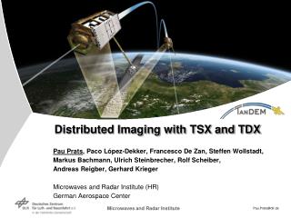
Pau Prats , Paco López-Dekker, Francesco De Zan, Steffen Wollstadt, Markus Bachmann, Ulrich Steinbrecher, Rolf Scheiber, Andreas Reigber, Gerhard Krieger Microwaves and Radar Institute (HR) German Aerospace Center. Distributed Imaging with TSX and TDX. Motivation.

Distributed Imaging with TSX and TDX
E N D
Presentation Transcript
Pau Prats, Paco López-Dekker, Francesco De Zan, Steffen Wollstadt, Markus Bachmann, Ulrich Steinbrecher, Rolf Scheiber, Andreas Reigber, Gerhard Krieger Microwaves and Radar Institute (HR) German Aerospace Center Distributed Imaging with TSX and TDX
Motivation • Future SAR missions will exploit bi- and multistatic SAR systems. • Such systems increase the potential, reliability and flexibility of future SAR missions. • Potential: frequent monitoring, wide-swath imaging, single-pass interferometry, enhanced products (e.g. in terms of resolution). • Perform new experiments! ;c) G. Krieger and A. Moreira, “Spaceborne bi- and multistatic SAR: potential and challenges”, IEE Proc.-Radar Sonar Navig., vol. 153, no. 3, June 2006.
TerraSAR-X add on for Digital Elevation Measurements • SAR Interferometer • Close formation • Global DEM (HRTI-3)
Double Differential Interferometry Digital Beamforming TanDEM-X: Secondary Mission Objectives Bistatic SAR Imaging Polarimetric SAR Interferometry Sea ice monitoring Super Resolution Ground Moving Target Indication Crossed-orbits SAR Tomography B1 B2 B3
Some Experiments with Distributed Imaging • Demonstration of distributed imaging with the following experiments: • Range-resolution enhancement • Azimuth-resolution enhancement • Quad-pol synthesis with dual-pol acquisitions • Digital beamforming • Elaborated manual commanding of each experiment • Experiments performed during the monostatic commissioning phase: Baseline needs to be compensated 20 km ~ 3 s TDX TSX
TanDEM-X Commissioning Phase June‘10 July‘10 Aug‘10 Sep‘10 Oct‘10 Nov‘10 Dec‘10 TDX Orbit Drift16.000 km 20 km 20 km Formation Close Helix-Formation 300-400 m Launch 21 June EarlyOrbitPhase 6 Months Commissioning Phase First SAR Image 24 June (MET +3.6) Grg SegmentCheckout TDX Monostatic Comm. Phase First DEM 16 July (MET +25) Bi-static Commissioning Phase First single-pass bi-static DEM 2 October (MET +107) First bi-static SAR image 8 August (MET +48) DEM Acquisition First close formation DEM 19 October (MET +124)
Super Resolution in Range: Step-Frequency with TSX and TDX • Limitation: RF filter allows maximum band of 300 MHz • Advantages within limitation: • Increased SNR • Data rate distributed among satellites • Baseline compensation for proper coherent combination • Negligible spectral shift for current configurations (but nevertheless considered) 300 MHz TSX fr f0 - Df TDX fr f0 + Df fr f0
Super Resolution in Range: Step-Frequency with TSX and TDX Coregistration Common-band spectrum interferogram
Super Resolution in Range: Experimental Setup • Data takes over Sydney, Australia, on August 15 and 26, 2010
azimuth range Super Resolution in Range: Experimental Results
azimuth range Super Resolution in Range: Experimental Results (II) Common-band interferogram
azimuth range Super Resolution in Range: Experimental Results (III)
azimuth range Super Resolution in Range: Experimental Results (IV)
azimuth range Super Resolution in Range: Experimental Results (V)
azimuth range Super Resolution in Range: Experimental Results (VI) Interferometric coherence between synthesized images Interferometric phase between synthesized images
Super Resolution in Azimuth TSX fa fDC,1 TDX fa fDC,2 fa fDC,mean
Super Resolution in Azimuth: Experimental Setup • Data take over Neustrelitz, Germany, on September 20, 2010
Super Resolution in Azimuth: DTAR Analysis Maximum bandwidth DTAR: -19.91 dB TDX DTAR: -21.67 dB Twice the resolution DTAR: -21.42 dB TSX DTAR: -21.04 dB
azimuth range Super Resolution in Azimuth: Experimental Results (I)
azimuth range Super Resolution in Azimuth: Experimental Results (II) Common-band interferogram
azimuth range Super Resolution in Azimuth: Experimental Results (III)
azimuth range Super Resolution in Azimuth: Experimental Results (IV)
azimuth range range azimuth Super Resolution in Azimuth: Experimental Results (V)
Super Resolution in Azimuth: Experimental Results (VI) Measured resolutions over a corner reflector: • TSX: 2.97m • TDX: 2.97 m • Combined: 1.49 m
Quad-Pol Synthesis with Dual-Pol Acquisitions • Each satellite acquires a co-pol and a cross-pol channel, e.g. HH-VH and HV-VV • The cross-pol channel is used to estimate the calibration phase • Better SNR and DTAR when compared to the experimental quad-pol product using the dual receive antenna (DRA) mode • DLR’s E-SAR example: quad-pol synthesis at C-band with repeat-pass dual-pol acquisitions [1] E-SAR [1] R. Scheiber et al., “Radar data processing, quality analysis and level-1b product generation for AGRISAR and EAGLE campaigns,” in AGRISAR and EAGLE Campaigns Final Workshop, Noordwijk, The Netherlands, Oct. 15-16 2007.
azimuth range Quad-Pol Synthesis: Experimental Results • New acquisitions performed in bistatic mode are on their way.
Conclusion & Future Work • Proof of concept of several experiments with TSX and TDX • Range-resolution enhancement • Azimuth-resolution enhancement • Quad-pol synthesis with dual-pol acquisitions • Qual-pol synthesis with dual-pol acquisitions using bistatic data (close formation) • Further performance analyses, especially for the azimuth case • By doubling the PRF one can obtain simultaneously a resolution improvement in both dimensions • Digital beamforming with an interferometric baseline