Gas Chromatography
Gas Chromatography. 2004. Kim, Wang-Yu Ph.D. Interface Engineering Co., Ltd. - 이론과 실제 -. GC 의 정의. 두개의 상 ( 고정상 , 이동상 ) 사이에서 혼합물 각각의 성분이 분배 ( 혹은 흡착 ) 되는 정도가 다른 성질을 이용하여 각각의 성분을 분리하는 크로마토그래피 기술이다 . 이동상으로는 혼합물과 반응하지 않는 기체를 사용하는 것이 HPLC 와 크게 다른 점이다. GC vs. LC. Gas. Liquid.

Gas Chromatography
E N D
Presentation Transcript
Gas Chromatography 2004. Kim, Wang-Yu Ph.D. Interface Engineering Co., Ltd. -이론과 실제-
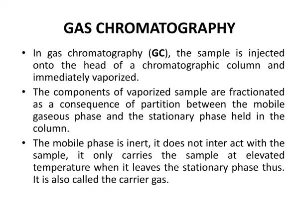
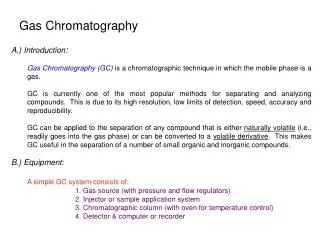
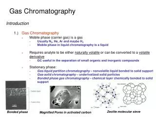
GC의 정의 • 두개의 상(고정상, 이동상) 사이에서 혼합물 각각의 성분이 분배(혹은 흡착)되는 정도가 다른 성질을 이용하여 각각의 성분을 분리하는 크로마토그래피 기술이다. 이동상으로는 혼합물과 반응하지 않는 기체를 사용하는 것이 HPLC와 크게 다른 점이다.
GC vs. LC Gas Liquid Mobile phase Sample state Gas Liquid Stationary phase Liquid or solid Liquid
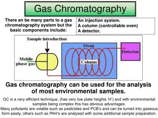
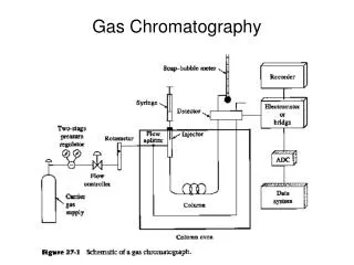
Inside GC Injecting and vaporizing Detecting Separating
Injection Port Septum Graphite ferrule Inlet liner Nut
Capillary columns 1. Stationary phase 2. Inner Diameter(mm) 3. Length(m) 4. Film Thickness(um)
FID Flame Ionization Detector
Open (Capillary) GC Column 종류 (단면) Packed Regular Wall Coated Open Tube (WCOT) Bead Conventional Porous Porous Layer Column Packed and Layer Open Tube (PLOT) Micropacked Bead
ubular (PLOT) L ayer pen T P orous O Carrier Gas ubular (WCOT) W all C oated O pen T Liquid Phase Capillary Column Types
GC column의 특성 1. Stationary phase 2. Inner Diameter(mm) 3. Length(m) 4. Film Thickness(um)
Polarity Solubility Phase = Solute High Phase ¹ Solute Low High solubility = High retention and capacity POLARITY
Benzene 8.1 Phenol 11.9 C12 C10 11.9 10.9 0 2 4 6 8 10 DISPERSION INTERACTIONKcal/mole DB-1 (non-polar)
DIPOLE INTERACTIONCompounds With Dipole Differences H H Cl H C=C C=C H Cl Cl Cl 1,2-dichloroethylene 1,1-dichloroethylene • Smaller differences require a stronger dipole phase
HYDROGEN BONDING INTERACTIONExample Compounds • Strong: alcohols, carboxylic acids, 1° and 2° amines • Moderate: aldehydes, esters, ketones • Weak: hydrocarbons, halocarbons, ethers
Phase Dipersion Dipole H Bonding Methyl Strong None None Phenyl Strong None Weak Cyanopropyl Strong Strong Moderate Trifluoropropyl Strong Moderate Weak PEG Strong Strong Moderate SELECTIVITYInteraction Strengths
Hydrogen Compounds Polar Aromatic Dipole Bonding Toluene no yes no induced Hexanol yes no yes yes Phenol yes yes yes yes Decane no no no no Naphthalene no yes no induced Dodecane no no no no COMPOUNDSProperties
6 2 4 1 3 5 50%Cyanopropyl 0 2 4 6 8 10 12 14 16 2 1 3 4 6 5 100% Methyl 0 2 4 6 8 10 12 14 16 50% CYANOPROPYL 1. Toluene2. Hexanol3. Phenol4. Decane (C10)5. Naphthalene6. Dodecane (C12) Strong DispersionStrong DipoleModerate H Bonding
Me O Si Me n Polysiloxanes(Methyl Substituted) % = # of sites on silicon atoms occupied 100 % methyl (HP-1, DB-1 etc.) Nonpolar
Me Ph O O O Si Si Ph Me m n Polysiloxanes(Phenyl methyl Substituted) 5% phenyl (HP-5, DB-5, etc.)35% phenyl (HP-35, DB-35, etc.)50% phenyl (HP-50+, DB-17, etc.) Nonpolar Mid-polar Mid-polar
Me R O O O Si Si R' Me n m Polysiloxanes(Cyanopropylphenyl methyl Substituted) 6% cyanopropylphenyl (HP-1301, DB-1301, etc.)14% cyanopropylphenyl (HP-1701, DB-1701etc.)50% cyanopropylphenyl (HP-225, DB-225, etc.) Mid-polar Mid-polar Polar
CH 3 Si O Si Si O O m n n CH CH 3 3 HP-17: 50% phenyl and 50% methyl siloxanevsHP-50+ : (50%)-Diphenyl (50%)-Dimethylpolysiloxane Two columns are different !!
H H HO - - C-C-O- -H H H Poly(ethylene) Glycol n 100% PEG (HP-WAX) Less stable than polysiloxanesUnique separation characteristics Polar
POLARITYSolubility And Retention C12 C10 Hexanol 100% Methyl(non-polar) 0 2 4 6 8 Same GC conditions Same column dimensions Only differ in stationary phase C10 C12 100% PEG(polar) Hexanol 0 2 4 6 8
1. Stationary phase 3. Length(m) 4. Film Thickness(um) 2. Inner Diameter(mm)
21.81 0.25 mm 0 5 10 15 20 16.06 0.32 mm 0 2 4 6 8 10 12 14 16 COLUMN DIAMETERRetention80°C isothermal Isothermal: Retention is inversely proportional to column diameterTemperature program: 1/3-1/2 of isothermal values
COLUMN DIAMETER(0.05~0.53mm) n =58,700 n =107,250 0.53 mm 0.32 mm Sample capacity : < 2 ug < 500 ng Instrumental condition
= r column radius ( m) d = film thickness ( m) f Phase Ratio The combined effect of the column diameter and film is , thickness described by the phase ratio. = r/2d f where
Column A: HP-624 30 0.32 1.8 m, mm, m HP part no. 19091V-413 Carrier: Helium, 40 (m/sec) Oven: 65° C Injection: Split Detector: FID Column B: HP-624 30 0.53 3 m, mm, m HP part no. 19095V-423 0 5 10 15 20 Time (min) Differing Column Inner Diameter, Equal Betas
1. Stationary phase 2. Inner Diameter(mm) 4. Film Thickness(um) 3. Length(m)
COLUMN LENGTHTheoretical Efficiency Length (m) N 15 71,430 30 142,860 60 285,720 0.25 mm IDN/m = 4762 (for k = 5)
R=1.16 R=0.84 R=1.68 2.29 min 8.73 min 4.82 min COLUMN LENGTH(10~120m)Resolution and Retention: Isothermal 15 m 30 m 60 m Double the plates, double the time but not double the the resolution
1. Stationary phase 2. Inner Diameter(mm) 3. Length(m) 4. Film Thickness(um)
FILM THICKNESS(0.1~5um)Retention: Isothermal 7.00 0.25 µm 0 2 4 6 8 Thermal stability Sample b.p. 25.00 1.00 µm 0 5 10 15 20 25
FILM THICKNESSBleed More stationary phase = More degradation products
CH3 H3C Si O HO CH3 CH3 CH3 CH3 CH3 Si Si Si Si Si Si O O O O CH3 CH3 CH3 CH3 CH3 CH3 CH3 CH3 CH3 CH3 CH3 CH3 CH3 CH3 O CH3 CH3 CH3 CH3 CH3 CH3 Si Si Si Si Si O Si Si OH O O O O O CH3 CH3 CH3 CH3 CH3 Si O Si O Si O Si OH CH3 H3C Si CH3 CH3 CH3 CH3 O O CH3 Si H3C Si O CH3 H3C “Back biting” Mechanism of Bleed Formation + Again
Four Types Of Low Bleed Phases Phases tailored to “mimic” currently existing polymers -Examples: DB-5ms, DB-35ms, DB-17ms New phases unrelated to any previously existing polymers -Example: DB-XLB Optimized manufacturing processes -Example: DB-1ms
Column Installation • Choosing ferrule • Cutting the capillary column • Inlet installation • Leak-checking • Outlet installation • Establishing flow • Conditioning
Choosing ferrule • Cutting the capillary column • Inlet installation • Leak-checking • Outlet installation • Establishing flow • Conditioning Ferrule • Graphite(100%) - 450℃ - general purpose and reused - FID, NPD, ECD - Not good for Mass • Vespel(100%) - 280℃ - reused - for only isothermal operation
Choosing ferrule • Cutting the capillary column • Inlet installation • Leak-checking • Outlet installation • Establishing flow • Conditioning Cutting • Jagged silica edges or exposed polyimide cause adsorption and tailing peaks, so it is very important that the column ends are cut uniformly.
Choosing ferrule • Cutting the capillary column • Inlet installation • Leak-checking • Outlet installation • Establishing flow • Conditioning Inlet installation • 먼저 column nut를 capillary column에 끼우고 ferrule을 끼운다. • 3cm 이상 capillary가 나오게 한 후 먼저 inlet에 조여 capillary가 ferrule에 적당히 물리게 한다. • 일단 푼다. • capillary를 5mm정도 남겨놓고 자른다. • 다시 inlet에 연결한다. • 손으로 꽉 조인 상태에서 ¼~반바퀴 더 wrench로 돌린다. • 이동상을 흘렸을 때 이 부분에 Leak가 있을 경우 injector 압력 gauge가 올라가지 않는다.
Choosing ferrule • Cutting the capillary column • Inlet installation • Leak-checking • Outlet installation • Establishing flow • Conditioning Leak-checking Use acetone in vial
Choosing ferrule • Cutting the capillary column • Inlet installation • Leak-checking • Outlet installation • Establishing flow • Conditioning Outlet installation • 보통 detector jet orifice보다 1-3mm 아래쪽에 column end가 있게 한다(보통 capillary를 detector안쪽으로 끝까지 밀어 넣어 넣은 후 2mm정도 뒤로 뺀다). • column nut와 ferrule을 끼우는 요령은 inlet과 같다.
Choosing ferrule • Cutting the capillary column • Inlet installation • Leak-checking • Outlet installation • Establishing flow • Conditioning Carrier gas Flow
Choosing ferrule • Cutting the capillary column • Inlet installation • Leak-checking • Outlet installation • Establishing flow • Conditioning Conditioning • 40℃ start and 5~10℃/min • below 20~25℃
Storage • septum on each end of the column • Especially for PEG type column