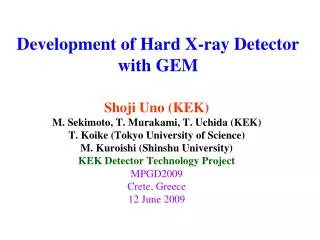
GEM Detector
GEM Detector. Shoji Uno KEK. Wire Chamber. Detector for charged tracks Popular detector in the particle physics, like a Belle-CDC Simple structure using thin wires. Electron. Anode wire. Gas amplification near anode wire.

GEM Detector
E N D
Presentation Transcript
GEM Detector Shoji Uno KEK
Wire Chamber • Detector for charged tracks • Popular detector in the particle physics, like a Belle-CDC • Simple structure using thin wires
Electron Anode wire Gas amplification near anode wire • High electric field (>30kV/cm) can be obtained easily due to using thin wire (diameter ~0.03mm) • Energy of electron become higher for high electric field near wire. • Electron can produce another electron for ionization. • Number of electrons increases due to multi steps of this process. (gas amplification、 electric avalanche) • Gas gain up to ~105 can be obtained easily.
Recent gas chamber • Requirement • High incident rate • One wire covers wide region. • Wire spacing > ~1mm • Length >~10cm Need more space • Pure two-dimensional readout • Wire has some limitation due to straight wire LHCATLAS
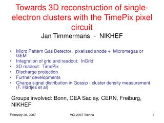
New development • Development MPGD(MicroPattern Gasdetector) • Gas multiplication in high electric field with other than wire • 3 types • MSGC(MicroStripGasChamber) • MICROMEGAS(MicromeshGaseousDetector) • GEM(GasElectron Multiplier)
GEM (Gas Electron Multiplier) Double side flexible printed circuit board Electric field Hole diameter70mm Hole pitch140mm Thickness50mm Cu thickness5mm • Developed by F.Sauli (CERN) in 1997. • NIMA 386(1997)531
Flexible shape Fabio Sauli
Configuration for GEM detector Readout
High counting capability ワイヤーチェンバー GEM
Application of GEM • Feature of GEM • Pure two-dimensional readout → Image • Multi-layer structure • Stable operation • Multi-conversion-layer(Neutral Charged) • High counting capability • GEM can be applied for many other fields, not only high energy physics.
X-ray detector X-ray absorption tomography Crystal structure analysis using X-ray
Photon sensor • Same function for photomultiplier • Usable in Magnetic field • Fine segmentation in readout • Cheap and Larger • Key issue is photo-electric surface in gas volume. • Under developement
55Fe (5.9 keV X-ray) DRIFT 10 mm GEM1 1mm TRANSFER 1 ~2 mm GEM2 TRANSFER 2 ~2 mm GEM3 ~2 mm INDUCTION PCB TestChamber PCB □15mm×15mm 36=6×6 2200pF 2200pF GAS Ar-CH4(90/10) (P-10) Ar-CO2(70/30)
Pulse shape 200ns Signal from GEM foil 130mV Signal from Readout pad
P10 Ar-CO2 Effective gas gain and resolution 55Fe Ar-CH4(90/10) Sigma/Mean = 8.8% Number of events DVGEM=325V Edrift = 0.5kV/cm Etransfer = 1.6kV/cm Einduction= 3.3kV/cm Pedestal=104.6 ADC counts
Gas gain vs various parameters P10 Ar-CO2 P10 Ar-CO2 EI ED Ar-CO2 P10 Ar-CO2 EI ET
Electric field dependence in drift region In case of weak field In case of strong field ED=500V/cm ED=3000V/cm ΔVGEM=320V ΔVGEM=320V EI=1000V/cm EI=1000V/cm 55Fe (5.9 keV X-ray) Drift region ED ΔVGEM=360V ET=1.6kV/cm EI=3.6kV/cm Electric field (kV/cm) Ionization occurs in drift region Electrons enter into GEM holes. Collection Efficiency
ADC SUMADC ADC counts 63 0 Channel σ=359.7±0.4 μm Charge distribution ΔVgem=330V Ed= 0.5 kV/cm Et=1.65 kV/cm Ei= 3.3 kV/cm P10 Normalized ADC counts One event mm -1 0 1 dX (each strip – C.O.G) dX(各strip-C.O.G) σ=181.2±0.3 μm ΔVgem=370V Ed= 0.5 kV/cm Et=2.59kV/cm Ei=5.18 kV/cm Ar-CO2 (70/30) Normalized ADC counts mm -1 0 1 dX(各strip-C.O.G) dX (each strip – C.O.G)
Charge spread 0.546mm/√cm P10 MagBoltz P10 0.258mm /√cm Ar-CO2 Ar-CO2 Diffusion is dominant factor.
Application of GEM Shoji Uno (KEK-DTP) • Neutron detector • X-ray detector • Soft X ray • Hard X ray • Light
Application to Neutron Detector • Expensive 3He Gas is not necessary. • No pressure vessel • Free readout pattern • High resolution • Position and Time • Insensitive against g-ray • Capability against high counting rate Ar-CO2 Cathode plate With B10 B10 coated GEMs Normal GEM Readout board
Chamber structure Ar/CO2 = 70:30 Thickness of Boron-10 : 4.4mm 2.0mm + 0.6mm ×4 8 mm Al - 10B cathode ED = 1.5 kV/cm 1 mm ( 0.5mm ) 150V (75V) B GEM 1 240V 1 mm ET = 1.5 kV/cm 150V B GEM 2 240V 1 mm ET = 1.5 kV/cm 150V GEM 1 400V ET = 2.2 kV/cm 2 mm 440V GEM 2 370V EI = 4.0kV/cm 2 mm 800V X(120) +Y (120) strips 0.8mm pitch Readout strip
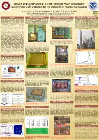
I/F One HV cable Three LV cables One Ethernet cable Electronics 8 ASIC chips + 1 FPGA FE2009 ASIC : KEK-DTP Data transfer and Control through Ethernet SiTCP by T. Uchida(KEK) Using Note-PC Present Detector System Ethernet Electronics Low Voltage GEM Chamber Compact and Portable System T.Uchida et. al., "Prototype of a Compact Imaging System for GEMdetectors," was published on IEEE TNS 55(2008)2698.
Data samples The beam profile and its TOF distribution L = 18789 mm ~ 18.8 m L: distance from the source to the detector An image of a cadmium slit and its TOF distribution (Å) L = 18789 mm 27 mm Events from 1.5 Å to 8 Å are selected 60 mm Cd cutoff The thickness of the slit ~0.5 mm This image is produced with a wavelength cut. (Å) Our system can obtain a 2D image and its TOF at the same time. 11
Energy Selective Neutron Radiography Resonance absorption region(E>1eV) Bragg Edge region (Thermal and cold)
Resonance absorption imaging By T. Kai (JAEA) et al. at BL10 in J-PARC
One more demonstration TEST Sample Ratio of ToF spectrums with/without sample EURO coin gold coin Imaging data with around 450msec ToF