Comprehensive RF Management Software for Optimizing Network Deployment and Performance
Enhance your network performance and deployment efficiency with our RF Management Software. Offering easy planning for Wi-Fi installations, it features predicted heatmaps for optimal site planning, manual and automatic AP placement, and integrated switch configuration. Monitor real-time trends, troubleshoot issues with complete infrastructure visibility, and ensure security with rogue AP detection. Generate planning reports and configurations for installers, facilitating streamlined network setup and management, all from a user-friendly Windows XP application.

Comprehensive RF Management Software for Optimizing Network Deployment and Performance
E N D
Presentation Transcript
RF Management Software Tools for optimizing network deployment and performance
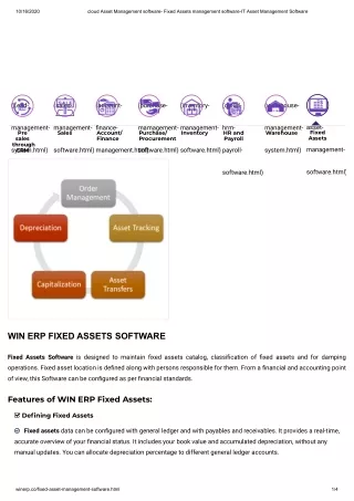
Features & Functionality Easy planning of Wi-Fi installations Predicted heatmaps for Site Planning - Manual and auto APs placement Integrated with Switch configuration Near real time/time trends for various status/statistics View RF heatmaps Plan & Install Visualization Presence Monitor & Troubleshooting Faster troubleshooting, Complete visibility View presence – status and location of wireless infrastructure and clients RF Manager Security Audit Intelligent reporting Better administration Rogue AP detection, Control over WLAN intrusions Reporting
RF Manager v1.0 Feature Set • Windows XP Application • Site planning supported on all Symbol Infrastructure Products: • WS5100, AP-5131 • Single Floor Plan support • User Configurable Parameters • Import site map and configuration of deployment area • Input desired RF characteristics • AP placement or select number of APs • Predicted Site Planning • Predicted AP placement • Predicted Heat Maps • Locality of Clients: location relative to associated AP • Troubleshooting RF Statistics for Infrastructure and clients • Intrusion Detection Statistics
Planning • Predicted Heatmaps for Planning • Manual Placement of AP’s • Auto Placement of AP’s • Planning Reports generated for Installers • PDF format • Configurations Generated that can be cut and pasted into the Wireless devices. • CLI Commands
Planning • User ‘admin’ logins and selects the planning tab and then creates a new project (or opens an existing project). • Planning has only one sub tab – “802.11 Network” • After opening a new or existing project, user ‘admin’ defines various characteristics and infrastructure for the site by clicking on various tool bar icons such as: • Specify floor map for the desired coverage area • Floor Plan: Jpeg / GIF / TIFF • Scale of floor plan • Specify RF characteristics • Country of Deployment • Frequency Band • AP Antenna type • User configurable prediction resolution (range: 1foot to 15 feet)
Planning …Contd. • Desired number of APs (optional only for Auto Placement) • Desired dataspeed i.e. MU Bit rate (e..g. 36, 54) (optional only for Auto Placement) • Identify by dragging cursor over the floor map and adding • Don’t care areas • RF environment zones – silent, moderate or noisy • Special zones – can’t place areas, high MU count, minimum PHY rate desired • Specify environmental attributes are added: • Walls (line segments) (Cubes should not be drawn as walls as everything today is 2D i.e. all objects are full height/everything on the same plane) • RF Blockers (rectangles only) • Metal (rectangles only)
Planning …Contd. • After ‘admin’ has defined the site: • For manual placement: • ‘admin’ starts placing APs and specifies their location, power etc. • ‘admin’ specifies antenna for each AP and can also specify antenna type(gain) • ‘admin’ does ‘calculate heatmap. • For auto placement: • ‘admin’ selects ‘auto placement’. ‘admin’ can specify either fixed # of APs OR desired bitspeed. It also asks for # of optimize iterations. After user has selected then auto placement is done and user is shown the predicted heatmap. • ‘admin’ can also click on ‘optmize’ to optimize further. • If no further optimization desired then ‘admin’ saves the project as well as:
Planning …Contd. • Generates Report that can be shared with the installer to install APs. • Generates Wireless Switch Config that can be added to the wireless switch (by cut and paste or pushing the config if the switch is live in the network (stretch)) • ‘admin’ at this stage may also save ‘connectivity parameters’ of the network (such as wireless switch/AP ip address, snmp user name, snmp password etc.) so that the ‘support’ user can later monitor or troubleshoot that network. • Please note that channel selection mode for each AP is always ACS.
Troubleshooting Functionality4 – Catagories/Tabs • Troubleshooting Statistics(over 200 stats): • Key Performance Indicators • Cluster Information • Signal Strength • AP Utilization • MU Utilization • WLAN Utilization • Service Interruptions • Security • Rogue AP • IDS statistcs
Troubleshooting Functionality4 – Categories/Tabs - continued • Presence • Heatmap based on current AP configurations/statistics • MU location based on AP • Status of the infrastructure for project • Search • Find all devices matching a search expression • Check applicable status/statistics and location • ‘search expression’ can be part of MAC address, IP address or description (MU, AP or WLAN description)
Windows XP WS5100 (WING) Server side Client side Core Servlet/CGI AJAX WEB Browser IE, Firefox AP 5131 HTTP Software & Installation • Software is provided as Windows XP Software package. • End users (administrators or support users) access it via popular web browsers (Firefox, IE) by pointing to the machine on which it is installed. SNMP
Software Installation - Licensing • Installation will be for Windows XP • Software will require a ‘License Key’ • Currently working with IT
KPI – Key Performance Indicators • RF Coverage • Indicates PHY Rate as available in planned areas • Load Balancing • Indicates if AP or MU load balancing is happening or load is SKEWED • Redundancy Quotient • Indicates if there are enough standby switches or APs in healing neighborhood to cover in event of FAILURE or higher retries • Security Threat Level • Indicates degree of Intrusion and Rogue Activity • Network Utilization • Indicates network bandwidth usage
Common RF Manager Tasks • Planning • Preparing for troubleshooting • Proactive Troubleshooting: How is my network doing ? Should I drill down in something specific? • Reactive Troubleshooting: When a user calls that (s)he is having problems with the Wi-Fi network – its slow ! • Reactive Troubleshooting: When a user calls that (s)he is having problems with a specific AP! • Reactive Troubleshooting: What is security threat level of my RF Site? • Reactive Troubleshooting: Poor Coverage
Reactive Troubleshooting- Various Scenarios One of the following problem is reported by a specific user OR in a specific area • Unable to associate • Slow Association • Does not get IP address after association • Getting dropped frequently (observing association and disassociation frequently ) • Connecting at low rates i.e. slow network • Facing too much roaming
RF Manager v2.0 Planned Features • Real-time Heat maps • MU and AP height definition • AP-AP Validation • Location based on Triangulation • Define multiple floors • WIPS Sensor Coverage • WS 2000 Support
? uestions