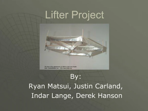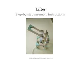
Lifter
Lifter. Step-by-step assembly instructions. Contents of the Workshop-Lifter Kit. Wooden pieces (⅜” cross-section): 7 X 12” Green corner gussets: 2 cards Syringes, 20cc: 2 (1 has a hole in the plunger) Plastic Tubing: 1 length Wooden dowel, 3/16” diam.: 2 X 5”; 1 X 3” Axle Holders: 16


Lifter
E N D
Presentation Transcript
Lifter Step-by-step assembly instructions (c) 2010 National Fluid Power Association
Contents of the Workshop-Lifter Kit Wooden pieces (⅜” cross-section): 7 X 12” Green corner gussets: 2 cards Syringes, 20cc: 2 (1 has a hole in the plunger) Plastic Tubing: 1 length Wooden dowel, 3/16” diam.: 2 X 5”; 1 X 3” Axle Holders: 16 Syringe Holder: 1 Mini-washers: 8 Stirring Sticks: 2 Plus a small piece of sandpaper (c) 2010 National Fluid Power Association
Cutting list for Workshop Lifter • From the 7 pieces provided in each kit measure and mark the following: • 4 pieces 8” long • 3 pieces 4” long • 2 pieces 3⅝” long • 7 pieces 3¼” long • 2 pieces 1½” long • 3 pieces 1” long • Measure carefully twice, check the measurements again and then cut! (c) 2010 National Fluid Power Association
Assembly plans for slides 5 - 8 (c) 2010 National Fluid Power Association
Glue a 3 ¼” piece to another 3 ¼” piece and then glue a 3⅝” piece to a 4” piece to form two “L” shapes. The smaller “L” will measure 3¼” by 3⅝” externally and the larger “L” will measure 4” by 4” externally. Joining the pieces is accomplished using a green triangle and a small application of wood glue. Use one corner gusset or triangle only for each “L” at this time.Repeat the construction and make another two “L” shapes with the same measurements. (c) 2010 National Fluid Power Association
Glue an 8” piece into both “L” shapes made from the 3⅝” and 4” pieces.Lay it alongside the 4” side and glue it there as well as into the corner gusset. Turn the “L” shapes carefully over and glue a gusset onto the corner. (c) 2010 National Fluid Power Association
Glue the “L” shapes made from the 3 ¼” and 3 ¼” pieces into the “L” shapes with the 8” pieces. Use 6 corner gussets for each frame, three on each side. (c) 2010 National Fluid Power Association
Connect the uprights to one of the frames by first making three “double-corner” gussets. These “double-corner” gussets are glued to three corners to form holders for the uprights. Use two corner gussets folded in the middle for each upright (c) 2010 National Fluid Power Association
Once the holders are in place and they are dry, glue a 3 ¼” piece into each to form an upright perpendicular to the frame. There will be three uprights on the frame. Three more “double-corner” gussets are glued to the corners of the second frame. (c) 2010 National Fluid Power Association
Once the uprights are glued in place and their glue is dry, the second frame can be glued into position. It is “berthed” with the uprights on the first frame and glued in place at each corner. A 4” piece is glued into place “behind” the 8” pieces using 2 corner gussets on each of the two corners. (c) 2010 National Fluid Power Association
Glue an axle holder with a hole in it to the structure 2 ½” from the edge furthest from the 8” pieces. First mark the axle holder where the center of the hole joins the middle of the longest side. Use this to align with the measure of 2 ½” on the structure. (c) 2010 National Fluid Power Association
Using the same measurement glue another axle holder to the other side of the structure and before it dries check that a dowel or axle, passing through both holes of the axle holders, is perpendicular to the structure and parallel to the 4” piece. Glue an axle holder on the inside of the frame on both sides and use an axle to ensure smooth rotation. (c) 2010 National Fluid Power Association
Glue an axle holder onto the outside of an 8” support so that the center of the hole is 1 ½” from the end and the hole points away from the structure. (c) 2010 National Fluid Power Association
Using the same technique and using a 5”axle to check alignment, glue another axle holder on the opposite side. The axle should also be parallel to the 4” piece. Then glue two other axle holders on the insides of each 8” support. Once again check alignment using a 5” axle. (c) 2010 National Fluid Power Association
Glue together three 1” pieces using glue between the pieces. Glue a corner triangular gusset to a largest surface, cutting the excess corner and gluing it into the gap. Glue two axle holders to opposite sides and trim. The holes of the axle holders should stand above the larger surface that does not have the corner gusset glued to it. This is the platform that will hold the acting syringe. (c) 2010 National Fluid Power Association
Once everything is dry test in the structure using the 5”axle and ensure smooth rotation. (c) 2010 National Fluid Power Association
Make the arm by connecting two 8” pieces and two 1 ½” pieces. Use 8 corner gussets – four on each side. (c) 2010 National Fluid Power Association
On this 8” by 2 ¼” frame glue an axle holder in place so that its smallest angle touches the corner of the frame. Use a 5” axle to align and glue another axle holder on the outside of the opposite side. Test that the 5”axle sits across the frame parallel to the shortest end. (c) 2010 National Fluid Power Association
Glue another axle holder in place so that its smallest angle touches the other smallest angle of the first axle holder glued to the frame. In the same way and using the 3” axle align and glue in place another axle holder on the outside of the opposite side. Follow by aligning and gluing in place two more axle holders on the inside of the frame. The four axle holders must allow for a smooth rotation by the 3 “axle. (c) 2010 National Fluid Power Association
There are a number of steps in assembling the mechanism. The first is to identify the syringe that has a hole drilled in its plunger. The 3” axle fits through this hole and should turn in it. The axle and plunger fit between the double axle holders on the 8” arm and the outside, protruding axle is secured using a mini-washer on each end. (c) 2010 National Fluid Power Association
Remove the backing from the syringe clip to reveal a sticky pad. Carefully place the pad onto the green surface of the platform made from 1”pieces and apply some pressure until the clip is secure. Place the barrel of the syringe into the clip so that the clip aligns with the ’15’ mark or thereabouts and the lip stands proud. (c) 2010 National Fluid Power Association
Mount the syringe platform onto the structure so the lip points toward the 8” uprights and the barrel is above the axle. Secure with four mini-washers, two securing the syringe platform and two securing the axle ends on the outside of the structure. (c) 2010 National Fluid Power Association
Carefully insert the plunger into the barrel of the syringe until the holes at the end align with the holes in the axle holders glued to the 8” uprights on the structure. Once aligned, carefully insert the axle through all six holes. The axle is secured with a mini-washer at each end. (c) 2010 National Fluid Power Association
To operate the mechanism attach the length of plastic tubing to the end of the acting syringe that is now housed in the structure. The other syringe should be fully extended before it is connected to the other end of the tubing. Gently push the plunger down. This syringe drives the acting syringe. (c) 2010 National Fluid Power Association
LIFTER - open (c) 2010 National Fluid Power Association
LIFTER - closed (c) 2010 National Fluid Power Association