Multi-Core Design Automation Challenges
280 likes | 456 Vues
Multi-Core Design Automation Challenges. John Darringer IBM T. J. Watson Research Center Yorktown Heights, NY, USA. DAC 2007. Device Performance. 200. Recent Historical Trend. 100. Application. System Level. FPG. Chip Level. Production Date. 20. 1998. 2000. 2002. 2004. 2006.

Multi-Core Design Automation Challenges
E N D
Presentation Transcript
Multi-Core Design Automation Challenges John Darringer IBM T. J. Watson Research Center Yorktown Heights, NY, USA DAC 2007
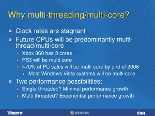
Device Performance 200 Recent Historical Trend 100 Application System Level FPG Chip Level Production Date 20 1998 2000 2002 2004 2006 2008 Technology System Performance Requires An Integrated Approach Languages, Software Tuning Efficient Programming Middleware Dynamic optimization Assist Threads Fast Computation Power Optimization Compiler Support Compiler Support Multiple Cores SMT Accelerators Power Management Interconnect Circuits • Scaling no longer provides traditional performance boost • Power limits everything • Advances will come from entire performance stack Packaging, Cooling New Devices Dense SRAM, eDRAM Optics Memory
Innovation in System Design Power 6 4.7 Ghz-2007 Power 5 Multi-Thread-2004 Power 4 Multi-Core-2001 CELL Accelerators-2006
Blades Trend to Modular Application Optimized Systems Accelerator Core Memory Cache SMP ... • Growing use of diverse modular components • Chip integration may evolve to component assembly • Challenge is in system-level design • Optimizing architecture for specific applications
Multi-Core ASICs • Multi-core ASIC SoCs are common today • Address broad range of markets • Enables high functional integration • Provides rapid time to market • One example from 2004 • Cisco Silicon Packet Processor • 188 32-bit RISC processors • 47 BIPS
Multi-Core Processors • Power efficient, reusable cores • Application matched accelerators • Flexible scaleable interconnect • Optimized memory hierarchy • High speed I/O • Energy management • Deliver system performance • Rapid chip assembly to serve diverse markets
CHALLENGE • Design Automation • Custom design efficiency • AISC productivity • Design and verification • System Design • Continued performance growth • Increasing power efficiency • Optimizing for new applications • Enablers • Physical Architecture • Integrated Early Analysis • Multi-Core Verification
Physical Architecture • Complement logical architecture • Streamline chip integration • Plan for interconnect • Provide predictable results • Multiple strategies • Fixed layout per block • Parametric or generated • Extended synthesis Example Logical Architecture Example Physical Architecture
Modular Components • Components need self-contained vertical stack • with clean interfaces to enable automated integration ComponentFabric Interface FutureComponent Current“Component” Mixed Fabric and Component Function;Custom Interface ComponentFunction Current Chips Future Chips Custom crafting of clock, data, and power meshes Automated connection with parametric fabric
Custom Design • Careful interconnect design • Communication • Clock distribution • Power and ground • Better power efficiency • Clock gating, Power gating • Detailed transistor sizing • High bandwidth memory and I/O • Higher frequency operation
Core Core Core Core Core Core Core Core Challenges of Modular Design • Custom Layout • Flexible shape and orientation • Optimum mesh for power and clock • Distributed communication and test • Manually optimized • Modular Layout • Constrained shape and orientation • Separate power and clock per core • Parametric interconnect fabric • Automatic connection to fabric
Custom Clock Design • Distribution network • Latches and clocked gates • Control skew and jitter • Minimize power • Survive variation and noise • Interconnect models • Inductance critical • Transmission line • Buffer placement • Hand optimized • Still an art Phillip Restle
Custom Power Distribution • Distribute to all devices • Multiple voltage domains • Simulate detailed power demand • Model chip and package • Consider ground coupling • Balance mesh and trees • Allocate decoupling capacitors • Focus on resonant frequency • Explore clock/power gating scenarios Howard Chen
Challenges of Modular Design • Custom Wiring • Optimized over chip • Resources shared • Variation minimized • Complex analysis and integration • Modular Wiring • Optimized at block level • Fixed resource allocation • Some variation in results • Requires automated integration
Spectrum of Strategies Modular Reuse Extended Synthesis Fixed physical architecture • Careful block design • Custom within block • Automated block connect • Predictable results • Good for planned cases • Stresses design Fixed Layout …. Parametric ….. Generated Generated physical architecture • More abstract layout • Heavy physical synthesis • Unique block configuration • Results will vary • Flexible restructuring • Stresses tools
Systems Demand Early Analysis • To explore many more options • Cores, Accelerators, Interconnect, Memory Hierarchy, … • To consider many design criteria simultaneously • Power, Performance, Latency, Hotspots, Reliability, … • To optimize system for specific market • Environment exists for early functional modeling • But today’s tools are not linked to physical design
Early System Analysis Assumptions Design Floorplan Performance Models Interconnect Analysis Design Team Power Analysis Thermal Analysis Package Technology Implementation • Loosely coupled disciplines with multiple experts and distinct models
Performance Modeling Is Changing • New parallel workloads emerging • Execution vs. trace driven • Shifting to multi-core designs • Stresses balance of model performance and accuracy • Complex interconnect fabric and memory hierarchy • Bus, switch, network, asynchronous,… • Increasing use of SystemC • For early software development and component sharing
Early Physical Planning is Essential • Interconnect requires full chip layout • Estimate component area before implementation • Need more accurate methods • Have to plan for all facilities to predict chip size • Placement coupled to many factors • Interconnect performance • Power • Thermal and reliability concerns • Yield
Modeling Interconnects in Multi-Core Designs • Interconnect delays • Effect performance • Depend on placement • Require accurate modeling Core Core Interconnect Delays Cache Cache Interconnect Fabric Memory Controller Async/Sync Interface with Parametric delay Cache Cache Core Core
Power is Key Criteria, but Hard to Predict • Need estimate before implementation • Voltage/Frequency scaling, Voltage islands,clock gating, leakage • Not just core, but many diverse chip components • Core, cache, interconnect, controllers, I/O, pervasive • Model “interesting” states and transitions • Scale known implementations • Complex measurement process for calibration • Requires data from chip layout
Integrated Early System Analysis Design Team • Couple all forms of early analysis • Share data in central repository • Industry standard data model • Open Access • Hand-off to chip integration • Assumptions, blocks, layout, … • Graphic interface for editing • Stage is set for optimization Design Floorplan Package Technology Assumptions Results Performance Power Interconnect Thermal Optimize Handoff Implementation
Core Core Core Core Multi-Core Verification • Verification has always been the greatest challenge • Complexity grows with each generation • Challenge is to exploit reuse with multi-core designs • Requires clear interface definition Core Core Verification System Verification Traditional Approach Multi-Core Approach
Core Verification • Complexity growing • Clock/Power gating, Voltage and frequency scaling • Formal methods are used • Checking RTL = netlist • Checking assertions • Proving implementation equivalent to reference model • Simulation still dominates • Need higher level of specification • Improve quality • Stretch synthesis and verification tools • Reuse verification environment
System Verification • More complex systems • Many cores, accelerators, networks, asynchronous links • Memory and network contention is critical area • Formal methods have made impact • Verifying abstract memory protocols • Simulation is still the final check • Need system-level test case generation • Use system knowledge to expose resource contention issues
Summary • Exciting and challenging times • Designing application optimized multi-core systems • Delivering custom efficiency with ASIC productivity • Focus areas • Physical Architecture to streamline chip integration • Integrated Early Analysis to explore design space • Multi-core verification that exploits reuse • Long history of invention in today’s RTL flow • Innovation is needed now at the system level
Acknowledgements • Thanks to the following people • Emrah Acar, Reinaldo Bergamaschi, Pradip Bose, Howard Chen, Nagu Dhanwada, Steven German, Steve Kosonocky, Indira Nair, Ruchir Puri, Phillip Restle, Albert Ruehli, Michael Vinov.