Smart Cane IEEE Design Presentation
Smart Cane IEEE Design Presentation. Lauren Bell, Jessica Davila, Jake Luckman, William McIntyre, Aaron Vogel. Introductions. Lauren Bell – Mechanical Engineer Jessica Davila – Industrial Engineer Jake Luckman – Mechanical Engineer


Smart Cane IEEE Design Presentation
E N D
Presentation Transcript
Smart CaneIEEE Design Presentation Lauren Bell, Jessica Davila, Jake Luckman, William McIntyre, Aaron Vogel
Introductions • Lauren Bell – Mechanical Engineer • Jessica Davila – Industrial Engineer • Jake Luckman – Mechanical Engineer • William McIntyre – Electrical Engineer • Aaron Vogel – Mechanical Engineer
Agenda • Problem Description • Design Challenge • Potential Concepts • Critical Design Decisions • Final Concept • System Operation • Testing and Traceability • Project Management • Conclusion • Acknowledgements
Problem Description Safe and easy navigation in the world is difficult for the blind and deaf/blind Project Goal Expensive Training Required Inexpensive Intuitive Limited Situation Feedback Excellent Situation Feedback COMMON SOLUTIONS
Design Challenge… …To design, fabricate, assemble and validate a ‘haptic handle’ • To be attached to a traditional cane • Provide directional feedback to blind and deaf/blind users
Potential Concepts Brainstorming and benchmarking yielded the following likely candidates… • Track Ball • Piston Push Feedback • Torque ‘Jerk’ • Scroll Navigation • Magnetic Force Feedback
Scroll Navigation Pros • Easier to feel direction • Better directional feedback • Can be used with gloves Cons • May inhibit index finger haptic ability Screw-in cap Battery Housing Microcontroller Continuous servo Scroll Transmission
Mock Ups • Final Concept Ideas • Finger Bump Scroll • Palm Bump Roller • Final Concept Selection • Palm Roller
Design Considerations Customer desires needed to be transformed into technical requirements…
Design Considerations • Pressure on System • Bump Characteristics • Stress • Motor • Power Management • Microcontroller
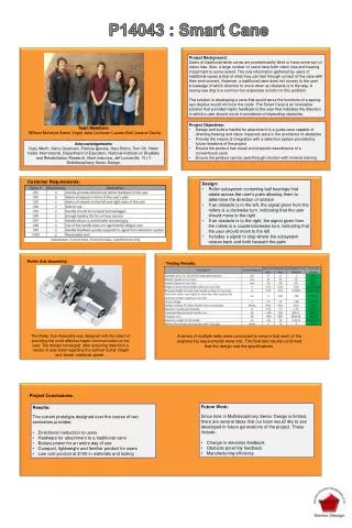
Design Grip Pressure Spec • Ensure handle functions under excessive grip • Measure pressure of displaced air for rough idea • Median pressure ~3 psi • Compare to Grip Pressure Study* • FSR sensors on glove • “Crush grip” measured on 50mm diameter handle • 5 male and 5 female adults • Maximum pressure ~3.1 psi Design made to withstand at least 3 psi. Tao Guo qiang; Li Jun yuan; Jiang Xian feng, "Research on virtual testing of hand pressure distribution for handle grasp," Mechatronic Science, Electric Engineering and Computer (MEC), 2011 International Conference on, pp.1610,1613, 19-22 Aug. 201
Bump Characteristics Analysis Sensitivity Comfort Through testing, effective bump height and speed was determined.
Motor Requirements • Maximum moment occurs when: • Grip reaches maximum design pressure • Pressure force is perpendicular to contact point • Palm contact area is maximum on roller • Two rollers contact the palm • Maximum moment caused by worst case scenario design pressure • 50.1 oz-in Selected motor met all design requirements.
Roller Analysis • Bumps per rotation • Servo to Roller Spacing • Effectiveness of our model – Audience?
Roller and Pins Force/Stress Analysis Rollers and pins withstand force and stress under worst case scenarios.
Testing and Traceability System has passed all tests
Testing and Traceability Prototype meets all non-technical requirements
Risk Curve All risks were tracked and managed.
ProjectPlan/Work Dispersion Project plan was tracked and work was properly distributed .
Conclusion • Desired cane handle objective was met
Recommendations • Complete cane with integration to sensors • Improve handle to provide feedback on changes in elevation and proximity of obstacles.
Acknowledgements • Guides • Gary Werth • Gerry Garavuso • Customers • Dr. Patricia Iglesias • Gary Behm • Tom Oh • Professor Mark Indovina • Jeff Lonneville
Attractive/Repulsive Magnetism Navigation Pros • Easier to feel direction • Better directional feedback • Can be used with gloves Cons • Possible power limitations • No indication of proximity (acting alone) Screw-in cap Battery housing Microcontroller Wire windings with ferrous cores
Piston Navigation Screw-in cap Pros • Easier to feel direction • Better directional feedback • Can be used with gloves Cons • Heavier • No indication of proximity (acting alone) • May inhibit index finger haptic ability Standard servo Battery Housing Push piston Drive shaft Microcontroller
Track Ball Navigation Screw-in cap Pros • Easier to feel direction • Better directional feedback • Can be used with gloves Cons • Heavier • Less compact • May inhibit index finger haptic ability Microcontroller Battery Housing Continuous servos & transmission shafts Track ball
Torque Handle Navigation Screw-in cap Pros • Easier to feel direction • Better directional feedback • Can be used with gloves Cons • Heavier • Moment of inertia/torque concern Transmission Standard servo Microcontroller Battery housing