Implementation of a MPC on a deethanizer
170 likes | 312 Vues
Implementation of a MPC on a deethanizer. Thanks to: Elvira Aske and Stig Strand, Statoil Aug. 2004. MPC implementation at Kårstø gas processing plant. Mainly distillation columns In-house MPC technology (“SEPTIC”)

Implementation of a MPC on a deethanizer
E N D
Presentation Transcript
Implementation of a MPC on a deethanizer Thanks to: Elvira Aske and Stig Strand, Statoil Aug. 2004
MPC implementation at Kårstø gas processing plant • Mainly distillation columns • In-house MPC technology (“SEPTIC”) • Karsto: So far 9 distillation column with MPC – 11 to go, plus MPC on some other systems, like steam production.
Controlled variable, optimized prediction Set point DV v MV CV Manipulated variable, optimized prediction Process u y model Current t Prediction horizon SEPTIC MPC CV soft constraint: y < ymax + RP 0 <= RP <= RPmax w*RP2 in objective • MV blocking size reduction • CV evaluation points size reduction • CV reference specifications tuning flexibility set point changes / disturbance rejection • Soft constraints and priority levels feasibility and tuning flexibility
Stepwise approach for implementation • Check and possible retuning of the existing controllers (PID). • Choose CV, MV and DV for the application • Logic connections to the process interface placed and tested • Develop estimators • Model identification. Step tests, (Have used: Tai-Ji ID tool) • Control specifications priorities • Tuning and model verifications • Operation under surveillance and operator training
1. Base control (PIDs) • Stabilize pressure: Use vapor draw-off (partial condenser) • Stabilize liquid levels: Use “LV”-configuration • Stabilize temperature profile: Control temperature at bottom • Note: This is a multicomponent separation with non-keys in the bottom, • so temperature changes a lot towards the bottom. • However, the sensitivity (gain) in the bottom is small, so this is against • the maximum gain rule ??? • Seems to work in practice, probably because of update from • estimator
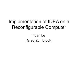
2. CV, MV, DV Heat ex Reflux drum Reflux pumps 34 23 28 10 1 20 21 16 LC TC LC FC PC FC LC FC PC FC 0 – 65% 65-100% CV Flare Fuel gas to boilers Propane Feed from stabilizators DV Product pumps MV MV Quality estimator CV CV LP Steam Quality estimator LP Condensate To Depropaniser
4. Composition (quality) estimators • Quality estimators to estimate the top and bottom compositions • Based on a combination of temperatures in the column x = i ki Ti Use log transformations on temperatures (T) and compositions (c) • Coefficients ki identified using ARX model fitting of dynamic test data. • Typical column: • “Binary end” (usually top) impurity needs about 2 temperatures – in general easy to establish • “Multicomponent end” (usually bottom) impurity needs 3-4 temperatures and in general more difficult to identify – test period often needed to get data with enough variation
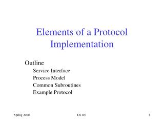
Temperature sensors C1 – CO2 A - C Heat ex Reflux drum Reflux pumps 1 20 34 21 23 16 10 28 FI TC LC PC TI AR PD FC FC FC FI TI TI TI FC LC TI TI TI TI TI PC 0 – 65% Deethaniser Train 300 65-100% Flare Propane Fuel gas to boilers Feed from stabilizators Product pumps LP Steam To Depropaniser LP Condensate
Top: Binary separation in this caseQuality estimator vs. gas chromatograph 7 temperatures 2 temperatures =little difference if the right temperatures are chosen
5. Step tests/Tai-Ji ID Reflux MV’s TC tray 1 C3 in top (estimator) C2 in bottom (estimator) CV’s Pressure valve position
Step tests/Tai-Ji ID MV1: Reflux MV2: T-SP CV1 C3-top CV2 C2-btm CV3 z-PC
Model in SEPTIC MV Model from MV to CV CV prediction adjustment of lower MV limit setpoint change
6. Control priorities Results: Predicts above SP MV1 SP Priority 2 Results: Predicts above SP MV2 SP Priority 2 Meet high limit DV Limit Priority 1
7. Tuning of a CV Logarithmic transformation of CV Model CV in mol % Bias Tuning parameters Control targets
The final test: MPC in closed-loop CV1 MV1 CV2 MV2 CV3 DV
Conclusion MPC • Generally simpler than previous advanced control • Well accepted by operators • Use of in-house technology and expertise successful