ms CAN Controller Area Network
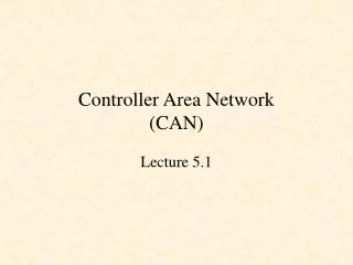
ms CAN Controller Area Network. SCI 1. SCI 1. ATD 1. ATD 0. 12K SRAM. 256K FLASEEPROM. Internal Bus. SPI 2 or PWM CH 4-7. SPI 1 or PWM CH 0-3. SPI 0. BKP INT MMI. PWM 8 CHAN. HCS12 CPU. SIM. CM BDM MEBI.

ms CAN Controller Area Network
E N D
Presentation Transcript
msCAN Controller Area Network
SCI 1 SCI 1 ATD 1 ATD 0 12K SRAM 256K FLASEEPROM Internal Bus SPI 2 or PWM CH 4-7 SPI 1 or PWM CH 0-3 SPI 0 BKP INT MMI PWM 8 CHAN HCS12 CPU SIM CM BDM MEBI PIM PLL PIT msCAN 4 or IIC msCAN 3 msCAN 2 msCAN 1 BDLC or msCAN 0 ECT 8 CHAN 4K BYTES EEPROM
msCAN Bus • Features: • Up to 5 msCAN Modules (msCAN) • 3 Tx message buffers each Automatically Mapped • 5 Background Rx Buffers • Programmable I/O modes • Maskable interrupts • Programmable loop-back for self test operation • Independent of the transmission medium (external transceiver is assumed) • Open network architecture • Multimaster concept • High immunity to EMI • Short latency time for high-priority messages • Low power sleep mode, with programmable wake up on bus activity Note: msCAN 0 is multiplexed with BDLC msCAN 4 is multiplexed with IIC.
CAN SPECIFICATION • LATEST REVISION (version 2.0) DIVIDED INTO PARTS A & B -PART A CONSISTS OF THE PREVIOUS SPECIFICATION REVISION (1.2): - Standard 11-bit Identifier Field - No specification for message filtering - Layered architecture description based on Bosch's internal model -PART B OUTLINES ENHANCEMENTS TO THE CAN PROTOCOL, INCLUDING: - Extended 29-bit Identifier Field - Some message filtering requirements - Layer description based on ISO/OSI reference model • MINIMUM CAN REQUIREMENTS INCLUDE COMPATIBILITY WITH SPECIFICATION VERSION 2.0, PART A • MOST CURRENT INDUSTRIAL APPLICATIONS USE THESTANDARD (11-BIT) IDENTIFIER FORMAT
CAN PROPERTIES • Serial communications protocol developed by Bosch, • initially for automotive multiplex wiring systems • • Message prioritization defined by the user • • Guaranteed minimum latency for highest priority • messages • • Multi - master protocol utilizes non - destructive • collision resolution to ensure the highest priority • message is transmitted onto bus • • Flexible system configuration allows the user to • create the network which best fits the application • • Error detection and error signaling features are • built into the CAN protocol, along with automatic • retransmission of corrupted messages • • Distinction between temporary errors and permanent • node failures prevents faulty nodes from causing • long-term disruptions of network traffic
msCAN - Layered Architecture • DATA LINK LAYER • LOGICAL LINK CONTROL (LLC) SUB-LAYER - Acceptance Filtering - Overload Notification - Recovery Management • MEDIUM ACCESS CONTROL (MAC) SUB-LAYER - Data Encapsulation/Decapsulation - Frame Coding (Bit Stuffing/Unstuffing) - Medium Access Management - Error Detection/Signaling - Acknowledgement - Serialization/Deserialization • PHYSICAL LAYER - Bit Encoding/Decoding - Bit Timing - Synchronization
msCAN Message Buffer Organization Receiver Rx0 RxBG Rx1 msCAN Rx2 RxBG - Receive Background Buffer RxFG - Receive Foreground Buffer Rx3 Rx4 RxFG RxF CPU Tx0 TxBG TxE0 TxBG - Transmit Background Buffer TxFG - Transmit Foreground Buffer Priority Tx Buffer Pointer Tx1 Transmitter TxFG TxE1 msCAN Priority Note: All Tx Buffers map to same address Tx2 TxBG TxE2 CPU Priority
Tx Buffer 0 Priority Register Tx Buffer 1 Priority Register Identifier Filtering Tx Buffer 2 Priority Register 2 x 32 bits or 4 x 16 bits msCAN12 Buffer Scheme msCAN Receive / Transmit Engine Internal Priority Scheduling HCS12 Memory Mapped I/O Rx Buffer or 8 x 8 bits Rx Buffer 5X FIFO * HCS12 FILTERING IS 2x THAT OF THE HC08
Requirements of a CAN Controller Microcontroller Message filtering + buffering CAN Transmit Receive Engine CPU Interface Simple user interface to CPU Message filtering and buffering Protocol handling Physical layer interface Control + status Physical interface CANH TX RX CAN bus CANL H/W Errors
DATA BYTE 0 DATA BYTE 1 DATA BYTE 2 DATA BYTE 3 DATA BYTE 4 DATA BYTE 5 DATA BYTE 6 DATA BYTE 7 DLC[3:0] Tx Buffer Priority Reg. Time Stamp Message Buffer Structure • ID[28:18] SRR IDE ID[17:15] • ID[14:0] RTR CONTROL/STATUS ID_HIGH ID_LOW $00x1 $00x3 $00x5 $00x7 $00x9 $00xB $00xD $00xF EXTENDED ID $00x0 $00x2 $00x4 $00x6 $00x8 $00xA $00xC $00xE STANDARD ID • ID[10 :0] RTR IDE 0 0 0 • Reserved $00x2 $00x4 $00x1 $00x3
Extended Format Frames • Field Description • Time Stamp Contains a copy of the high byte of the free running timer captured • at the beginning of the identifier field of the buffer frame on CAN bus. • ID[28:18]/[17:15] Contains 14 MS Bits of Extended identifier. • Substitute Remote Contains a fixed recessive bit, used only in extended format. It should • Request (SRR) be set to ‘1’ for TX buffers. It will be stored as received in the RX buffers • ID Extended Should be set to ‘1’ for extended formats, ‘0’ otherwise. • (IDE) • ID(14:0) Bits[14:0] of the extended identifier field. • Remote Transmission • Request (RTR) 0 = Data frame, 1 = Remote frame
Standard Format Frames Field Description Time Stamp The ID LOW word, which is not needed for standard format, is used in a standard format buffer to store the value of the free-running timer which is captured at the beginning of the identifier field of the frame on the CAN bus. ID(28:18) Contains bits (28:18) of the identifier, located in the ID HIGH word of the message buffer. The four least significant bits in this register (corresponding to the IDE bit and ID(17:15) for an extended identifier message) must all be written as logic zeros to ensure proper operation of the msCAN. RTR This bit is located in the ID HIGH word of the message buffer; 0 = data frame, 1 = remote frame. RTR/SRR Bit Treatment If the msCAN transmits this bit as a one and receives it as a zero, an “arbitration loss” is indicated. If the msCAN transmits this bit as a zero and is receives it as a one, a bit error is indicated. If the msCAN transmits a value and receives a matching response, a successful bit transmission is indicated.
Frame Types • A Data Frame is used to transmit data onto the multiplex bus; this is the frame used most often in a CAN network • A Remote Frame is used to request a data frame from another node on the multiplex bus • An Error Frame will be transmitted by any node which detects an error, corrupting the frame being transmitted • An Overload Frame is used by a node which desires an extra delay between data or remote frames to allow it time to prepare to transmit a frame
ARBITRATION FIELD 12 BITS FOR STANDARD ID 32 BITS FOR EXTENDED ID 1 BIT
MESSAGE ARBITRATION • If multiple nodes transmit simultaneously, bit-wise non-destructive arbitration during the message identifier field resolves the conflict • Identifier defines the priority of the message as well as the target address • Node transmitting a recessive level but detecting a dominant level immediately halts transmission and becomes a receiver • Remote frame is lower priority than data frame • Any loss of arbitration after the arbitration field will be interpreted as an error, and an error frame will be transmitted
ERROR DETECTION • Multiple Error Detection Features: - 15-bit cyclical redundancy check (CRC) - Bit stuffing - Each node verifies message framing • All global errors detected • Up to 5 randomly distributed errors will be detected • Corrupted messages are flagged by any nodes detecting the error • Corrupted messages are automatically retransmitted • Recovery time from error detection to start of message retransmission is a maximum of 29 bit times
FAULT CONFINEMENT • Separate error counters for transmit and receive errors • Error counters incremented by 1 or 8, decremented by 1 • 3 possible bus states: - Error active - both error counts < 128 - Error passive - either transmit or receive error count > 127 - Bus off - transmit error count > 255 • Once error-free bus traffic resumes, nodes can recover from error states
ERROR SIGNALING • Error Active Node - Transmits active error flag during error frame - Only waits for intermission period during inter-frame space • Error Passive Node - Transmits passive error flag during error frame - Must wait for "suspend transmission" period as well as intermission during inter-frame space • Bus Off Node - Output drivers switched off - Will not participate in bus traffic, only allowed to monitor bus - Bus off node will return to error active status following detection of 128 consecutive periods of 11 recessive bits
BIT TIME SYNC_SEG PROP_SEG PHASE_SEG1 PHASE_SEG2 Transmit Point Sample Point Bit Timing • SYNC_SEG : The bit edge is expected to lie within this segment ; always 1 time quantum (CAN clock period) long. • PROP_SEG : Allowance for physical delays. Programmable from 1 to 8 TQ long. PROP_SEG >= 2 x (bus propagation delay + input comparator delay + output driver delay) • PHASE_SEG (1, 2) : Defines position of the Sample Point. May be adjusted to compensate for edge phase errors • PHASE_SEG1: Programmable from 1 to 8 time quanta long. • PHASE_SEG2: Is the greater of PHASE_SEG1 and the INFORMATION PROCESSING TIME. • SAMPLE POINT : Bus value is taken as the value of the bit • INFORMATION PROCESSING TIME: Less than or equal to 2 time quanta. • BIT TIME : Bit Time = SYNC_SEG + PROP_SEG + PHASE_SEG1 + PHASE_SEG2
msCAN Bus Timing (1 of 2) CANBTR0 - Bus Timing Register 0 Address Offset $0002 Synchronization Jump Width Baud Rate Prescaler
msCAN Bit Timing (2 of 2) CANBTR1 - Bus Timing Register 1 SAMP: 1 or 3 samples per bit TSEG1 is determined by TSEG13...TSEG10 TSEG2 is determined by TSEG22...TSEG20 Address Offset $0002
SYNCHRONIZATION • HARD SYNCHRONIZATION - Occurs when recessive to dominant edge occurs during bus idle - Internal bit time is started with Sync-Seg • Resynchronization - Occurs on all other recessive to dominant edges (and optionally dominant to recessive edges) - Phase-Seg 1 is lengthened or Phase-Seg 2 is shortened depending upon phase error • Phase Error - e - e = 0 If edge lies within Sync-Seg - e > 0 If edge lies after Sync-Seg - e < 0 If edge lies before Sync-Seg • Resynchronization Jump Width - The maximum amount by which Phase-Seg 1 may be lengthened or Phase-Seg 2 may be shortened
Resynchronization (2) r CAN Bus d Receiver bit timing S PS P1 P2 S PS P1 P2 S PS P1 P2 S PS P1 P2 S PS P1 P2 Sample points Positive Phase Error PHASE_SEG1 lengthened Negative Phase Error PHASE_SEG2 shortened
CANPHYSICAL LAYER REQUIREMENTS • CAN Protocol does not specify physical layer • No specified transceiver, user's network characteristics define transceiver requirements • Acceptable physical media can include, though not limited to: - Twisted Pair, Shielded or Unshielded - Single Wire - Fiber Optic Cable - Transformer Coupled to power lines • Acceptable transmission rates range from 5k to1m bit/sec • Most implementations use NRZ bit formatting over twisted pair bus • Three different automotive physical layers exist: ISO11898 Differential, ISOxxxx Fault-Tolerant, J2411 Single Wire
msCAN MB Identifier Registers bit 7 bit 6 bit 5 bit4 bit 3 bit 2 bit 1 bit 0 Address Offset $00x0 $00x1 $00x2 $00x3 IDR0 ID28 ID27 ID26 ID25 ID24 ID23 ID22 ID21 IDR1 ID20 ID19 ID18 ID17 ID16 ID15 IDE RTR/SRR IDR2 ID14 ID13 ID12 ID11 ID10 ID9 ID8 ID7 ID6 ID5 ID4 ID3 ID2 ID1 ID0 RTR IDR3 Standard Identifier (IDE = 0) / Base Identifier (IDE = 1) Extended Identifier (SRR = 1) The priority of an Identifier is highest for the smallest binary value ie. logic ‘0’ is transmitted as dominant. The 7 most significant bits (ID28 - ID22) must not all be ‘1’ (recessive).
msCAN MB Data Registers bit 7 bit 6 bit 5 bit4 bit 3 bit 2 bit 1 bit 0 DR0..7 D7 D6 D5 D4 D3 D2 D1 D0 DLR DLC3 DLC2 DLC1 DLC0 Data Length Code should be 0..8 only. TBPR P7 P5 P6 P4 P1 P3 P2 P0 Priority Register for Transmit Buffers only. $00 is highest priority.
msCAN Acceptance Registers (2x32 Bit Filter) Address Offset $0010 $0011 $0012 $0013 $0018 $0019 $001A $001B bit 7 bit 6 bit 5 bit4 bit 3 bit 2 bit 1 bit 0 AC27 AC26 AC25 AC24 AC23 AC22 AC21 AC28 CANIDAR0 AC19 AC18 AC17 AC16 AC15 IDE CANIDAR1 AC20 RTR/SRR AC13 AC12 AC11 AC10 AC9 AC8 AC7 AC14 CANIDAR2 AC6 AC5 AC4 AC3 AC2 AC1 AC0 RTR CANIDAR3 CANIDAR4 AC28 AC27 AC26 AC25 AC24 AC23 AC22 AC21 AC20 AC19 AC18 AC17 AC16 AC15 CANIDAR5 IDE RTR/SRR AC13 AC12 AC11 AC10 AC9 AC8 AC7 AC14 CANIDAR6 CANIDAR7 AC6 AC5 AC4 AC3 AC2 AC1 AC0 RTR Extended Identifier Standard Identifier / Base Identifier
msCAN Message Acceptance Mask bit 7 bit 6 bit 5 bit4 bit 3 bit 2 bit 1 bit 0 Address Offset $0014 $0015 $0016 $0017 $001C $001D $001E $001F CANIDMAR0 AM28 AM27 AM26 AM25 AM24 AM23 AM22 AM21 CANIDMAR1 AM20 AM19 AM18 IDE AM17 AM16 AM15 RTR/SRR CANIDMAR2 AM14 AM13 AM12 AM11 AM10 AM9 AM8 AM7 AM6 AM5 AM4 AM3 AM2 AM1 AM0 RTR CANIDMAR3 CANIDMAR4 AM28 AM27 AM26 AM25 AM24 AM23 AM22 AM21 CANIDMAR5 AM20 AM19 AM18 IDE AM17 AM16 AM15 RTR/SRR CANIDMAR6 AM14 AM13 AM12 AM11 AM10 AM9 AM8 AM7 AM6 AM5 AM4 AM3 AM2 AM1 AM0 RTR CANIDMAR7 Standard Identifier / Base Identifier Extended Identifier
msCAN Message Acceptance Registers (4x16 bit filter) bit 7 bit 6 bit 5 bit4 bit 3 bit 2 bit 1 bit 0 Address Offset $0010 $0011 $0012 $0013 $0018 $0019 $001A $001B CANIDMAR0 AM28 AM27 AM26 AM25 AM24 AM23 AM22 AM21 CANIDMAR1 AM16 AM17 AM15 AM20 AM19 AM18 IDE RTR/SRR CANIDMAR2 AM28 AM27 AM26 AM25 AM24 AM23 AM22 AM21 AM20 AM19 AM18 IDE AM17 AM16 AM15 CANIDMAR3 RTR/SRR CANIDMAR4 AM23 AM28 AM27 AM26 AM25 AM24 AM22 AM21 CANIDMAR5 AM20 AM19 AM18 IDE AM17 AM16 AM15 RTR/SRR CANIDMAR6 AM28 AM27 AM26 AM25 AM24 AM23 AM22 AM21 AM20 AM19 AM18 IDE AM17 AM16 AM15 RTR/SRR CANIDMAR7 Standard Identifier / Base Identifier Extended Identifier
msCAN Acceptance Registers (8x8 Bit Filter) bit 7 bit 6 bit 5 bit4 bit 3 bit 2 bit 1 bit 0 Address Offset $0010 $0011 $0012 $0013 $0018 $0019 $001A $001B CANIDMAR0 AM28 AM27 AM26 AM25 AM24 AM23 AM22 AM21 CANIDMAR1 AM25 AM28 AM27 AM26 AM24 AM23 AM22 AM21 CANIDMAR2 AM28 AM27 AM26 AM25 AM24 AM23 AM22 AM21 AM24 AM26 AM28 AM27 AM25 AM23 AM22 AM21 CANIDMAR3 CANIDMAR4 AM26 AM28 AM27 AM25 AM24 AM23 AM22 AM21 CANIDMAR5 AM25 AM28 AM27 AM26 AM24 AM23 AM22 AM21 CANIDMAR6 AM28 AM27 AM26 AM25 AM24 AM23 AM22 AM21 AM28 AM27 AM26 AM25 AM24 AM23 AM22 AM21 CANIDMAR7 Standard/Extended Identifier
msCAN Acceptance Filter • Each Acceptance Register has a corresponding Acceptance Mask Register. • Any bit set in an Acceptance Mask Register means that bit in the Acceptance Register is masked, ie. not compared with the Message Identifier to determine acceptance. • Only bits in the Acceptance Register which are not masked are compared with the message Identifier to determine acceptance. • 16 bit filter. Bit 3 of CANIDAR1 is ‘1’ and bit 3 of CANIDMR1 is ‘0’ • Therefore IDE must be ‘1’ to be accepted ie Standard Format Identifier. • In this case CIDMR1 bits 2,1,0 must all be ‘1’ (mask). • As above, plus CANIDMR1 bit 4 is ‘1’ (mask). • Therefore Data Frames or Remote Frames accepted.
msCAN Acceptance Control Register bit 7 bit 6 bit 5 bit4 bit 3 bit 2 bit 1 bit 0 CANIIDAC IDAM1 IDAM0 IDHIT2 IDHIT1 IDHIT0 Identifier Acceptance Mode Settings Identifier Acceptance Hit Indication
msCAN Receive Process 1) Set SFTRST. 2) Configure Acceptance Filter. 3) Enable Receive interrupt. 4) Clear SFTRST. Receive Interrupt: 1) Read Identifier. 2) Read Data Field (if not Remote Frame). 3) Read Timer Stamp if enabled. 4) Release Receive buffer.
msCAN Transmit Control Address Offset $0006 bit 7 bit 6 bit 5 bit4 bit 3 bit 2 bit 1 bit 0 CANTFLG TXE2 TXE1 TXE0 TXEn = 1: Transmit buffer empty (sent or aborted). TXEn = 0: Transmit buffer full (not sent, scheduled). TXEIEn = 1: Enable transmit interrupt. ABTRQn = 1: Request abort of transmission. ABTAKn = 1: Message aborted (not sent). ABTAKn = 0: Message not aborted (sent). RST: 0…………………………………………………………0 1 1 1 $0007 TXEIE2 TXEIE1 TXEIE0 CANTIER RST: 0…………………………………………………………………………………...…………………0 $0008 ABTRQ1 ABTRQ0 CANTARQ ABTRQ2 RST: 0…………………………………………………………………………………...…………………0 CANTAAK ABTAK2 ABTAK1 ABTAK0 $0009 RST: 0…………………………………………………………………………………...…………………0 Write “1” to Clear Interrupt Flag
msCAN Transmit Process 1) Write Identifier, Data and Priority to empty transmit buffer. 2) Schedule buffer for transmission (clear TXEn). 3) Enable Transmit interrupt (set TXEIEn). • The transmit buffer with the lowest value (highest Priority) that is scheduled for transmission will arbitrate for CAN bus access during the next IFS. Transmit Interrupt: 1) Identify transmitted message buffer. 2) Disable Transmit interrupt. 3) Test ABTAK. 4) Read Time Stamp if enabled. 5) Load with new ID, data and schedule for transmission.
RSTAT1–RSTAT0 — Receiver Status Bits The values of the Error Counters control the actual bus status of the MSCAN. As soon as the Status Change Interrupt Flag (CSCIF) is set these bits indicate the appropriate receiver related bus status of the MSCAN. 11 = Bus Off : 255 > Transmit Error Counter 10 = RxERR: 127 < Receive Error Counter 01 = RxWRN: 96 < Receive Error Counter < 127. 00 = RxOK: 0 < Receive Error Counter < 96. TSTAT1–TSTAT0 — Transmitter Status Bits The values of the Error Counters control the actual bus status of the MSCAN. As soon as the Status Change Interrupt Flag (CSCIF) is set these bits indicate the appropriate transmitter related bus status of the MSCAN. 11 = Bus Off: 255 > Transmit Error Counter 10 = TxERR: 127 < Transmit Error Counter < 255 01 = TxWRN: 96 < Transmit Error Counter < 127 00 = TxOK: 0 < Transmit Error Counter < 96 msCAN Interrupt Control CANRFLG - Receiver Flag Register • WUPIF: Wakeup interrupt flag. • CSCIF: CAN Status Change Interrupt Flag • OVRIF: Overrun interrupt flag. • RXF: (Foreground) Receive buffer full. To clear the interrupt request Must write a “1” to clear corresponding bit, with the event that caused it to set is no longer valid CACRIER - Receiver Interrupt Enable Register
msCAN Control Register 0 RXFRM - Receive Frame 1= Valid message was received 0 = No message was received RXACT - Receiver Active 1 = msCAN is currently receiving a message 0 = msCAN is transmitting or idle CSWAI - msCAN stops in WAIT mode 1 = msCAN clock is stopped during Wait mode 0 = msCAN continues to run in Wait mode SYNCH - Synchronized Status 1 = msCAN is synchronized to CAN bus 0 = msCAN is not synchronized Address Offset $0000 bit 7 bit 6 bit 5 bit4 bit 3 bit 2 bit 1 bit 0 CANCTL0 RXFRM RXACT CSWAI SYNCH TIME WUPE SLPRQ INITRQ TIME - Timer Enable 1 = Internal timer enabled 0 = Internal timer is disabled WUPE - Wake-up Enable 1 = msCAN is able to start from sleep mode 0 = msCAN will not wake up from sleep mode and ignores bus traffic SLPRQ: SLEEP Mode Request. 1 = Put the msCAN to sleep 0 = msCAN functions normally INITRQ - Initialization Mode Request 1 = msCAN is in initialization mode 0 = Normal operation
msCAN Control Register 1 bit 7 bit 6 bit 5 bit4 bit 3 bit 2 bit 1 bit 0 CANE - msCAN Enable 1 = msCAN is enabled 0 = msCAN is disabled CLKSRC - msCAN Clock Source 1 = The msCAN clock source from IP bus clock 0 = The msCAN clock source from the OSC-CLK LOOPB: Internal loopback self test mode. 1 = Enable loop back mode 0 = Disable loop back mode LISTEN - Listen only Mode 1 = Listen only mode is active 0 = Normal operation Address Offset $0001 CANE CLKSRC 0 CANCTL1 LISTEN LOOPB WUPM SLPAK INITAK WUMP - Wake-up Mode 1 = msCAN wakes up the CPU upon detection of a dominant pulse that has a length of Twup while WUPE=1 0 = msCAN wakes the CPU on recessive to dominant edge on the CAN bus while WUPE =1 SLPAK - Sleep Mode Acknowledge 1 = The msCAN entered sleep mode 0 = msCAN is running INITAK - Initialization Mode Acknowledge 1 = Initialization mode is active 0 = Normal operation
msCAN Low Power Modes msCAN registers may still be accessed in SLEEP and Soft Reset modes. msCAN will generate a Wakeup interrupt only if SLPAK = 1 and WUPIE = 1 The message which wakes up the msCAN will not be received.
msCAN Error Counter Rx Error Counter Address Offset $000E $000F Tx Error Counter Rx & Tx Error Counters are Read Only when in sleep mode (SLPRQ = 1 & SLPAK =1) or in Initialization mode (INITRQ & INITAK)
CAN Engine Network (> 250kbps) CAN Body Network (< =125kbps) Sub Bus Network (< 50kbps) Light Motorola’s System Focus Mirror Application Code Lock Lock Window Lift OS Libraries Design Tools Development Tools Heating Task F OSEK-OS, -COM, -NM Climate Control OSEK OS Seat Task E Gateway Application Functionality ECU 1 OSEK COM/NM Wiper Heating Task D ECU 2 Drivers e.g. ignition Task C Interior Roof Lock Central Body Control ECU 3 Light Task B OSEK OS OSEK COM/NM OSEK OS Motorola Silicon Task A ECU 4 OSEK COM/NM Seat Motorola Focus Heating Instruments Heating Universal Motor Lock Lock Universal Panel Mirror
Example of CAN in a Door System HCS12 Vbatt Status X MC33186DW In1-I/O M MC7805 Vbatt 5v Y Mirror Position In2-I/O M Di21-I/O Vbatt Status MC33186DW In1-I/O M Mirror Fold In2-I/O Di21-I/O Vbatt EN CAN H Status MC33388DW MC33186DW STB CAN Bus In1-I/O M NERR CAN L TX In2-I/O RX Di21-I/O Door Lock Vbatt Status MC33186DW In1-I/O M In2-I/O Di21-I/O Vbatt MC33288DH Status Window Lift M In1-I/O Discrete Logic In2-I/O MTB75N06HD MTB75N06HD Di21-I/O