THE IEEE MAC SUB-LAYER – chapter 14
260 likes | 417 Vues
THE IEEE MAC SUB-LAYER – chapter 14. Dr. John P. Abraham Professor University of Texas, Panam. The data link layer (Layer 2 OSI). LLC Logical Link Control Refers upward to higher layers MAC Media Access Control refers downward to lower layers Media Access

THE IEEE MAC SUB-LAYER – chapter 14
E N D
Presentation Transcript
THE IEEE MAC SUB-LAYER – chapter 14 Dr. John P. Abraham Professor University of Texas, Panam
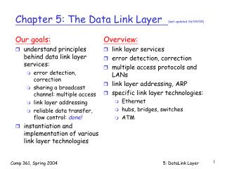
The data link layer (Layer 2 OSI) • LLC • Logical Link Control • Refers upward to higher layers • MAC • Media Access Control • refers downward to lower layers • Media Access • Determine how to get access when there is competition for the media. • MAC (Medium Access Control) sub-layer takes care of this problem • MAC is important in LANs where broadcast channels are used • MAC is the lower part of the data link layer (next to physical layer) • Mac sub-layer does not guarantee delivery
A Taxonomy of Mechanisms for Multi-Access • See the textbook for diagram p.242 • 1. Modified Form of Multiplexing Technique • 2. Distributed Allgorithm for Controlled Access • 3. Random Access Strategy
Static Channel Allocation • Works well for situations where set of communicating entities known in advance and does not change (not good for cell phones) • Traditional way to allow more than one person to use the medium is to use FDM • In Frequency division multiplexing, the total band width is divided among the total number of users • FDM works well when there is a small number of users • When users grow a fast busy signal is issued
Dynamic Channel Allocation • underlying assumptions of dynamic channel allocation • 1. Station Model • 2. Single Channel Assumption • 3. Collision Assumption • 4. Continuous time • 5. Slotted time
Station Model • Consists of N independent STATIONS • Each has programs that produce frames for transmission • Frames are generated at intervals • Once a frame is generated the station is locked until the frame is transmitted
Single Channel Assumption • Only one channel is available for all communication • All stations transmit on it and all stations receive on that channel
Collision Assumption • If two frames are transmitted simultaneously, they overlap in time and resulting signal is garbled. • All stations can detect collisions. • A collided frame must be retransmitted.
Continuous time • Frame transmission can start any time • There is no master clock controlling transmission (as opposed to slotted time discussed next)
Slotted time • Time is divided into discrete intervals (slots) • Frame transmission begins at the start of a time slot
Channelization Protocols • FDMA • TDMA • CDMA • Already discussed
Controlled Access Protocols • Polling • Using a centralized controller • Round Robin or Priority Order • Reservation – as used in satellite system • Token Passing-> See next slides.
802.4 token bus • Each station knows the address of the station to its left and right • The highest numbered station may send the first frame • Then it passes permission to its immediate neighbor by sending a special frame called a token. • The first station passes the token to the highest numbered one.
802.5 token Ring • Physical Ring • Token circulates
Random access /Multiple Access Protocols • ALOHA • PURE ALOHA • SLOTTED ALOHA • CARRIER SENSE MULTIPLE ACCESS PROTOCOLS (CSMA) • Persistent and Nonpersistent CSMA • CSMA with collision detection • Collision-Free Protocols • others
ALOHA • 1970 - Norman Abramson • University of Hawaii • Used ground based radio broadcasting. there are two frequencies: one for inbound and another for outbound. • Two versions of Aloha • Pure • Slotted
Pure ALOHA • Users may send on the inbound frequency whenever they have data to send • The central transmitter repeats it in on the outbound frequency for all stations to hear • If collisions occur, collided data will be destroyed • Sender can determine if the data was destroyed by listening to the channel (the sender can hear too). • If data was destroyed, re-send after waiting random amount of time
Slotted ALOHA • Divide time into discrete slots, each time slot is enough for one frame • Users agree on slot boundaries • A special station emits a signal at the start of each time slot to synchronize
Carrier Sense Multiple Access Protocols (CSMA) • Standard for Ethernet known as DIX (Digital, Intel, Xerox – 1978) • Originally described by Xerox PARC researchers in 1973 • Listen for a transmission • If the line is clear then transmit • Implementations: • Persistent, Non Persistent and p-persistent • CSMA with collision detection
Persistent • Listen, if busy wait until line is free • Transmit a frame • If collision occurred, wait for a random amount of time • Transmission time delay between two sending computers will cause the second computer not to hear the transmission.
Non-Persistent • Listen, if busy wait random amount of time and listen again until the line is free • This approach is less greedy than the Persistent one • This prevents two or more wanting to get on the line from doing so at the same time when the channel becomes free.
P-persistent CSMA • Slotted channels. • Listen, if free send at the beginning of the next slot
CSMA with Collision Detection (CSMA-CD) • Abort transmission as soon as collision is detected • Collision is detected by comparing received signal power to sent signal • If collision is detected, stop transmission and wait for random amount of time • CSMA/CD is used widely in LAN IEEE 802.3 is an example.
Collision free protocols • Bit-map protocol • A bit map with enough slots for all stations is passed around • Each station wanting to send a frame and if the frame is ready in the que, inserts a 1 bit into its reserved slot in the bit map. • Once station numbers of all who want to send is known they take turns in order. • Binary countdown
Binary countdown protocol • Each station is given a binary address • If a station wants to transmit a frame it broadcasts its address one bit at a time starting with the high order bit. • Bits from each station are Ored together the station address starting with the resulting 0 or 1 bit is allowed to go on. If two or more has the same bit then go to the next bit and so on.
CSMA/CA • Collision Avoidance instead of detection • For Wireless to avoid hidden stations • ----A------B------C All can transmit but A may not detect Cs transmission, so if A and C transmit at the same time, there would be collision. • Solution: C says read to send. B says clear to send, which is heard by A and therefore backs off from transmitting. C now can send.