Download
1 / 7
70 likes | 308 Vues
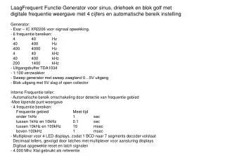
LaagFrequent Functie Generator voor sinus, driehoek en blok golf met digitale frequentie weergave met 4 cijfers en automatische bereik instelling Generator: Exar – IC XR2206 voor signaal opwekking. 6 frequentie bereiken: 4 40 Hz 40 400 Hz 400 4000 Hz 4 40 kHz 40 400 kHz

E N D
LaagFrequent Functie Generator voor sinus, driehoek en blok golf met • digitale frequentie weergave met 4 cijfers en automatische bereik instelling • Generator: • Exar – IC XR2206 voor signaal opwekking. • 6 frequentie bereiken: • 4 40 Hz • 40 400 Hz • 400 4000 Hz • 4 40 kHz • 40 400 kHz • 200 1400 kHz • Uitgangsbuffer TDA1034 • 1:100 verzwakker • Sweep generator met sweep zaagtand 0…5V uitgang • Blok uitgang met 5V slag of open collector • Interne Frequentie teller: • - Automatische bereik omschakeling door detectie van frequentie gebied • Mee lopende punt weergave • 4 frequentie bereiken: • Frequentie gebied Meet tijd • onder 1kHz 1 sec • tussen 1kHz en 10kHz 0.1 sec • tussen 10kHz en 100kHz 10 msec • boven 100kHz 1 msec • - Multiplexer voor 4 LED displays, zodat 1 BCD naar 7 segments decoder volstaat • Decimaal tellers, gevolgd door latches met multiplexer voor aansturing displays • Digitaal opgewekte reset en latch signalen • - 4.000 Mhz Xtal gebruikt als referentie
on / off out FREQ SWEEP LEVEL led 3 4 2 5 1 6 FREQ DISPL RANGE sweep on/off :100 o.c. TTL sweep out out 9 Block output buffer LF Function generator 4 10 Supply Frequency Counter low frequency Wave generator IC XR2206 5 Sine/Triangle output buffer 6 5 Sweep generator • Frequency ranges: • 4 – 40 Hz • 40 – 400 Hz • 400 – 4000 Hz • 4 – 40 kHz • 40 – 400 kHz • 200 – 1400 kHz 2 3 Voltage buffer and combiner 1 8 Controls, inputs, outputs: 1 Frequency setting 2 Sweep on/off 3 Sweep range 4 OC/TTL dig 5 OUT ana 6 Sine/triangle 7 Frequency range 1…6 8 Sweep output signal 9 block wave output 10 4 digit frequency display
+ - 40V unstab ≈ 230VAC Block diagram supply “+12V” 12V stab 24V stab “+5V” 5V stab 40V unstab “GND” -12V stab “-12V” pin aanzicht g e c a k3 k1 . . . . . . . . . . . . dp g f e d c b a k4 k3 k2 k1 dp f d b k4 k2 rode draad in lint kabel vooraan zicht display 4 3 2 1 a f b g e c d dp vooraan zicht display b g a f c e d dp kathode
Time Base RS1 RS0 4:1 mux TB : >1kHz 1s DP4 >10kHz 100ms DP3 >100kHz 10ms DP2 >1MHz 1ms DP1 y3 y2 y1 y0 10ms 1ms 1s 100ms :4 :10 :10 :10 :10 :10 :10 TB 4MHz .25u 1u 10u 100u 1m 10m 100m 1s D1 1m D2 ring counter D3 inverter buffer D4 c4 c3 c2 c1 DPn dp a b c d e f g a a a a BCD to 7 segment decoder f b f b f b f b D C B A D C B A g g g g x 1kHz e e e e c c c c d d d d dp dp dp dp >1kHz >10kHz >100kHz >1MHz 4 digit 7 segment common cathode led display
RST A1 A0 4:1 mux decimal counter CLK DP1n DP2n DP3n DP4n DPn latch O0 O1 O2 O3 MSB LEn 2x 4:1 mux A1 A0 COUNTER D C 2x 4:1 mux A1 A0 D4 D3 D2 D1 BIN 2 DEC A1 A0 B 1msec A
decimal point latch & decoder RST DP1n RS1 & Q 100kH D Qn DP3n & TBS8 DP2n & RS0 Q 10kH DP4n & 11 & D Qn 10 & 1ML TBS9 TBS7 <10k 1s 8750. DP1 <100k 100m 12.15 DP2 <1M 10m 131.7 DP3 >1M 1m 2.105 DP4 TBP freq input 10kH 100kH 1ML p10 p11 RS1 RS0 1sec <10kHz 0 0 1 1 1 0 1 DP1 100ms 10-100kHz 1 0 1 1 0 0 0 DP3 10ms 100-1000kHz 1 1 1 0 1 1 1 DP2 1ms >1000kHz 1 1 0 1 0 1 0 DP4 DP 4 3 2 1
Gate Circuit Reset Latch Circuit INPUT CLK LEn RSTn & & & TB TBP RST : 2 TB : <10kHz 1s >10kHz 100ms >100kHz 10ms >1MHz 1ms D Q0 D Q D Q D Q3 Qn Qn Qn Qn 1u (time base) shift-register Time Base Select Circuit 0.25u (time base) 100us : 2 : 2 O3 O2 O1 O0 : 2 O3 O2 O1 O0 : 10 : 10 R R R R R 1up 10up 100up R-TBS 1ML 100kL 10kL S S S Q D Q Q D Q Q D Q : 2 R R R 1MH 100kH 10kH Qn Qn Qn sr-ff latch