Integration Challenges in CLIC Module Technical Systems and RF Magnet Instrumentation
The CLIC Workshop in October 2009 presented compelling insights into the integration of technical systems within the CLIC module design. Utilizing a unique two-beam acceleration approach, the seminar highlighted the complexities of aligning RF power generation from a high-current electron beam with main beam instrumentation. Key challenges include layout designs, component interfaces, and maintaining performance under extreme conditions. Collaborative efforts among international institutions focused on finding baseline and alternative solutions to ensure seamless integration for optimal operational functionality.

Integration Challenges in CLIC Module Technical Systems and RF Magnet Instrumentation
E N D
Presentation Transcript
CLIC WORKSHOP October 2009 WG 5 «TECHNICAL SYSTEMS» CLIC MODULE INTEGRATION ISSUES A. Samoshkin 14-Oct-2009
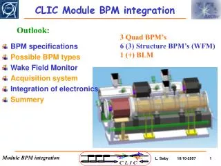
CLIC SYSTEMS R F MAGNET INSTRUMENTATION COORDINATE SUPPORTING ALIGNMENT AND STABILIZATION BEAM FEEDBACK VACUUM COOLING ASSEMBLY, TRANSPORT, INSTALLATION
CLIC MODULE Module design is based on two-beam acceleration idea, where the RF power is generated by a high current e-beam (DB) running parallel to the MB. This drive beam is decelerated in special power extraction structures (PETS) and the generated RF power is transferred to the main beam (AS). Each system must be compatible with others, which makes both, the design and integration complex & challenging. Baseline and alternative solution/s are being studied for each component of the technical system. Many issues appear often during integration • COLLABORATORS: • CEA/Saclay • CIEMAT • Dubna/JINR • UH/VTT • LAPP • NTUA • Pakistan, NCP • PSI • UPPSALA • Universityof Manchester • … • THE MAIN TASKS OF INTEGRATION: • overall layout, • space reservation, • number of components and their exact position and dimension • system integration; interfaces between components, interference of components • layout of special regions (i.e. DB turn-around loops)
MODULE TYPES CLIC Module Type1 154 per Linac 2 configurations under study Tank Version Module Type 3 477 per Linac Standard Module 8374 per Linac Module Type 4 731 per Linac Sealed Version Module Type 2 634 per Linac current baseline DB (100 A) 4 PETS, 2 Quads with BPM Each PETS feeds 2 AS MB (1 A) 8 acc. structures Main beam filling factor: 91% + special modules (damping region, modules with instrumentation and/or vacuum equipment) AS: based on CLIC ”G” disk damped (sealed version) (250 mm including 20 mm for interconnection)
CLIC MODULES T0, T1 & T4 Standard Module Module Type 1 Module Type 4
WAKE FIELD MONITOR COOLING TUBE SUPER-AS VAC ION PUMP LOAD CHOCK MODE FLANGE AS INTEGRATION VAC MANIFOLD VAC. RESERVOIR SPLITTER SUPPORT The design of the AS is driven by extreme performance requirements. The shape accuracy is relatively high (0.005 mm). Several features of different systems, such as vacuum, cooling, WFM have to be incorporated into design. The damping waveguide loads are in between of them. Two AS forming one Super-Structure (Ø 140 mm, L=2*230+20=480 mm) COOLING CHANNELS SPACE Ø80 AS WAVEGUIDE Ø140 DAMPING MATERIAL Detailed design under way
COOLING TUBE WFM A S LOAD AS INTEGRATION CMF WG FROM PETS RF SPLITTER WITH CMF SPLITTER VAC MANIFOLD • COMPLEXITY • Brazed disks with “compact” coupler • Micro-precision assembly • Cooling circuits (400 W per AS) • Wakefield monitor (1 WFM per AS) • Vacuum system (10-8 mbar) • Interconnection to MB Q (stabilization!) • Structure support (alignment) • Output WG with RF components (e.g. loads) • RF distribution (CMRS w/CMF) VAC MANIFOLD • Super-AS with internal cooling • Many systems to be integrated around the “Super-AS” • Super-AS with • external cooling
PETS INTEGRATION MINI-TANK OLD WAVEGUIDE TO AS COUPLER ON-OFF MECHANISM Joined with AS via waveguides & choke mode flange PETS octant (single bar) Assembled in mini-tank Equipped with couplers The octants assembly, mini-tank, on-off mechanism, vacuum system, cooling circuits, interconnection & supports are the subjects for integration CMF Welding
PETS INTEGRATION NEW • Structure (8 octants) with “compact” couplers • Mini-tank for structure • On-off mechanism ( t «off» 20 ms ) • Cooling circuits (size for 0.5% beam loss, couplers water-cooled, bars cooled by conduction) • RF distribution to AS • Vacuum system • Interconnection to BPM • Mini-tank support (fiducialisation) Octants assembly MINI-TANK COOLING CIRCUITS PETS “ON-OFF” mechanism combined with compact coupler COMPACT COUPLER REFLECTOR ACTUATOR
RF SPLITTER WITH CMF BELLOWS FROM PETS PETS (A) and AS (B) are connected via waveguides and RF splitter with choke mode flanges (CMF). CMF allows the power transmission without electrical contact between waveguides. This device should be flexible in order to permit independent alignment of two waveguides. TO AS TO AS GAP Requirements: WG interconnections between PETS and AS via CMF: X – shift: ± 0.25 mm Y – shift: ± 0.5 mm Z – shift: ± 0.5 mm Twist: < 5° A RF Design of CMRS (I. Syratchev & A. Cappelletti) B Hi Alexandre, it works even better than the one I sent you (input reflection is -54dB instead of -50dB). Best regards, Alessandro. RF splitter with Choke Mode Flanges
RF NETWORK DESIGN Waveguide length optimization is based on losses, phase advance and RF to beam timing considerations. The breakdown detectors must be integrated
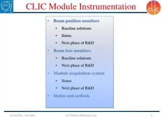
BEAM POSITION & WAKE FIELD MONITORS Limited space for BPM integration: 60-100 mm, 1 BPM per Quad, 1 WFM per AS (RMS position error 5 μm) Qty: DB: ~47000; MB: ~151000 units WFM HYBRID ANTENNA • MB BPM • Choke BPM: RF design made, mechanical design to be done (possible collaboration with RHUL) • FNAL Low-Q cavity BPM: wakefield calculation must be done very soon • DB BPM • Design will start in 2010 (collaboration with SLAC) BPM WFM: Mechanical design under way (collaboration with CEA-Saclay). AS with WFM in 2010 Detailed design is needed Q-BPM interconnection must be studied 50x100 mm space on the side along the module has been reserved for the electronics placement.
INSTRUMENTATION INVENTORY EDMS № 1009474 The signal and read-out frequencies still must be clarified and collected to the document.
QUADRUPOLES • MB: The magnets are needed in four different magnetic lengths (350, 850, 1350 & 1850mm). • Baseline: the beam pipe is attached to the magnet. The beam pipe centre needs to be aligned to the magnetic centre of the quad with an accuracy better than 30 μm. Transverse tolerance for pre-align. 17 µm at 1s, Stabilization: 1nm >1Hz in vertical&5nm >1Hz in horizontal direction at 1s. • DB: The active length specified is 150 mm. The total number of quads required for both linacs is ~42000. In current module design the DB Quad vertical size drives the beam height. DB MB Main Beam Quadrupole Nominal Gradient: 200 T/m Magnet bore Ø: 10 mm Final 3D models for magnets needed to be compatible with space allocation Drive Beam Quadrupole Nominal Gradient: 67 T/m Magnet bore: Ø23mm
MODULE OVERALL DIMENSIONS Oct-2009 Nov-2008 Direct influence on alignment, stability, transport and installation WIDTH: 1160vs1525 BEAM HEIGHT: 620vs730
SUPPORTING SYSTEM • BASELINE: • MB girders are not of the same length • MB Q support interrupts the MB girder • MB Q beam pipe and AS are connected by bellows
SUPPORTING SYSTEM • Current baseline is to support the AS and PETS with V-support connected to the SiC girder with rectangular cross-section. • Different shape configurations of the girders are considered. The girder material properties must provide a compromise between damping and stiffness (under investigation in a contact with several companies). • Supports must be compatible with thermal loads. The structures must stay within longitudinal and transversal tolerances under variable beam-loading conditions. • PETS support • AS support
SUPPORTING SYSTEM V-Supports for PETS Quad Support Under design, will be finalized with precision assembly study of AS V-Supports for AS • Requirement: • possibility to align MB & DB separately Temporary Module Support DB Girder MB Girder H2O Alignment Optical sensor Wire Alignment Space is reserved for MB Quad support (including alignment/stabilization/support) and alignment system
VACUUM LAYOUT Consideration on the quantity and overall dimensions of devices needed for creation and maintaining vacuum for the experiment is shown schematically. BASELINE: 10-8 mbar Sectoring valves must be integrated
VACUUM Vacuum system is under optimization Rough calculation of AS surface for pumping is done. The more precise (with the loads surface) must be finished as soon as the AS design done. VACUUM MANIFOLDS COMMON RESERVOIR ION PUMP S=0,47 m2 • The Quad vacuum chamber must be integrated. • Vacuum components supporting, decoupling from AS & PETS are our current challenging tasks.
VACUUM INTERCONNECTIONS • The MB and DB vacuum coupled via the common manifold and WG • The vacuum interconnections (intra-/inter-module): • MB: non-contacting interconnects acceptable. Short range wake-fields essentially equal to an iris. Long range wake-fields need damping. (under optimization) • DB: good contact is necessary due to high current. Concepts by C. Garion ready for detailed mechanical design study and implementation in the modules. To be integrated ASAP
ALIGNMENT Mechanical pre-alignment within ±0.1 mm (1s) Active pre-alignment: within ± 10 µm (3s) Concept: straight alignment reference over 20 km based on overlapping references • AS and PETS pre-aligned on independent girders (mono-girder alternative is also considered) • «Snake system», validated in CTF2. (Scaling needed due to higher load) • MB Quad pre-aligned independently. To be considered in integration: • Integration of the pre-alignment system/s in the modules, transport and installation • Fiducialisation (design and tests) Space reservation for the alignment equipment
STABILIZATION Stabilization requirement for the MB Quad (vertical tolerance: 1 nm >1 Hz) Compatibility of stabilization and pre-alignment systems to be considered TWO OPTIONS: CERN: rigid (active stabilization + fast nano-positioning) LAVISTA: soft support A proposal for the MB Quad fine alignment and stabilization has been suggested previously. Space is reserved accordingly. The problem is under study. The detailed study of vibration from different kind of sources as well as the components modal behaviour must be accomplished before integration of the MB Quad stabilisation system in the module .
MODULE COOLING LAYOUT • MB - AS in series, loads in series, Quad – in parallel • DB - PETS in series, Quads in series • The water circuits have a common inlet and outlet. Loads dimensions are adapted to the current module configuration and do not exceed 300mm in length and Ø 50mm. IN OUT Baseline cooling scheme (Super-AS) Valves still have to be integrated Due to high power dissipation: RF structures and magnets are water cooled. RF network must maintain its correct electrical length. (RF network cooling to be confirmed) An example of cooling circuits routing
PETS COOLING • Baseline: • cooling circuits external to PETS • cooling of PETS in series OLD Forced convection cooling – circuits inside the vacuum tank, outside the octants NEW New cooling configuration IN OUT Cooling channel and tubes integrated into compact coupler.
MODULE TRANSPORT & INSTALLATION The module assembly will be done on the surface. Each module has the cradles only on one end => the temporary support is needed. Strategy for Q modules to be agreed with SWG. An agreed strategy (with CES WG) is based on overhead lifting with spread beam. The two beams must be rigidly bound in order to maintain the alignment during transport (our concern – dedicated test in girder mock-up). The aim is to transport already interconnected modules. • The vertical interconnection plane between adjacent modules is included in integration requirements. (inter-girder connection: 30 mm) • The required space has been reserved for the alignment system. And we have to cross these zones during installation. • The lifting points still must be defined. • The transport solution needs to be in compliance with systems’ components. • The test area must be compatible with transport and installation tests requirements. • The transport and installation issues must be studied at the current design phase.
CONCLUSIONS • Integration of different systems in terms of space reservation has been finished. • Detailed design started for the main systems. • PETS concept is well advanced including the On-Off mechanism. • AS layout is under way. Integration conditions are specified. The system is very complex for design and integration. This is due to necessity to have many systems attached to AS. • Magnets dimensions should be confirmed soon. • RF network is well advanced. • PETS concept is well advanced including the On-Off mechanism. • The detailed design for supporting system is needed for better understanding of integration issues. • This is valid for the alignment and stabilization systems’ components as well. • The vacuum parts are defined, but the neighboring components give some restrictions. The optimization will be continued. • The instrumentation components design would require more attention. • Transport features to be studied and implemented. • Overview of the module systems now. Review in the nearest future (by Dec-2009). • Module baseline design definition by the end of Mar-2010. • CLIC modules in the lab from 2010 • Test modules in CLEX from 2011
GRATITUDE • I am very much obliged • to each system responsible • and all collaborators • for their contribution & cooperation !
THANK YOU ! THE END
AS (ALTERNATIVE) Depending on manufacturing strategy the AS could be produced of four quadrants, later assembled together. VAC. RESERVOIR AS IN QUADRANTS