Download
1 / 48
721 likes | 1.46k Vues
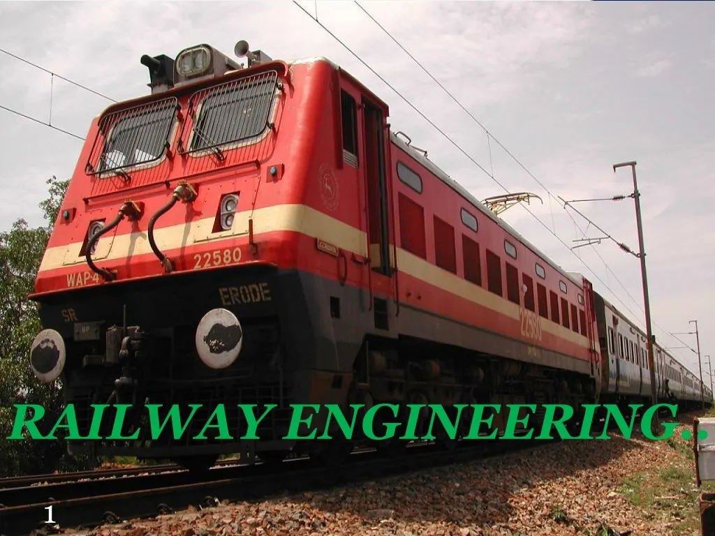
RAILWAY ENGINEERING. RAILWAY TRACK. COMPONENT PARTS OF A RAILWAY TRACK. RAILS. RAILS. Can be considered as steel girders for the purpose of carrying loads Made up of high carbon steel to withstand wear and tear Flat footed rails are mostly used in railway track. FUNCTIONS OF RAILS.

E N D
RAILWAY TRACK COMPONENT PARTS OF A RAILWAY TRACK
RAILS Can be considered as steel girders for the purpose of carrying loads Made up of high carbon steel to withstand wear and tear Flat footed rails are mostly used in railway track
FUNCTIONS OF RAILS Rails provide hard, smooth and unchanging surface for passage of heavy moving loads with minimum friction between steel rail and steel wheel Rails bear the stresses developed due to heavy vertical loads, lateral and braking forces and thermal stresses The rail material used is such that it gives minimum wear to avoid replacement charges and failure due to wear Rails transmit the loads to sleepers and consequently reduce pressure on ballast and formation below
REQUIREMENTS OF RAILS Rails should be designed for optimum nominal weight to provide for the most efficient distribution of metal in its various components
REQUIREMENTS (cntd..) The vertical stiffness should be high enough to transmit load to sleepers. The height of the rail should be adequate Rails should be capable of withstanding lateral forces. Large width of head and foot provides the rail with high lateral stiffness The depth of head of rail should be sufficient to allow for adequate margin of vertical wear. The wearing surface should be hard The web of rails should be sufficiently thick to bear the load coming to it and should provide adequate flexural rigidity in horizontal plane
REQUIREMENTS (cntd..) Foot should be wide enough so that the rails are stable against overturning especially on curves Bottom of the head and top of foot should be so as to enable the fish plates to transmit the vertical load efficiently from the head to the foot at rail joint The centre of gravity of rail section must lie approximately at mid height so that maximum tensile and compressive stresses are equal
REQUIREMENTS (cntd..) • Tensile strength of rail shouldn’t be less than 72 kg/m2 • To bring down the contact stresses to minimum level, the contact area between the rail and wheel should be as large as possible
TYPES OF RAIL SECTIONS Double headed rails Bull headed rails Flat footed rails
DOUBLE HEADED RAILS • First stage of development of rails • 3 parts: • Upper table • Web • Lower table • Similar to dumb bell section • Both upper and lower tables are identical • When upper table was worn out, the rail can be reversed thus lower table can be brought into use • Practically out of use • Made of wrought iron • Length varying from 610 cm to 732 cm
BULL HEADED RAIL Made up of steel Head is larger than foot Foot is designed only to hold the wooden keys with which rails are secured to chairs Extensively used in England Weight of standard rail or British rail is 47 kg/m of length for main lines and 42 kg/m length on branch lines Length of rail usually 18.29 m
FLAT FOOTED RAIL Foot is spread out to form a base Invented by Charles Vignoles in 1836 and hence also known as “Vignoles Rails” 90 % of railway track is made up of flat footed rails
Advantages of flat footed rails • Chairs • No chairs are required • Foot of rail directly spiked to sleepers • Stiffness • Vertically and laterally stiffer than BHR of equal weight especially on curves • Kinks • Less liable to develop kinks and maintains regular top surface than BHR • Cost • Cheaper than BHR • Load distribution • Distributes loads over large area • Results great track stability, longer life of rails and sleepers, reduced maintenance cost, less rail failures and few interruptions to traffic
WEAR ON RAILS • The moving of number of wheels of train on rail cause wear on rails • Depending on location wear of rail can be: • Wear of rails on top or head of rail • Wear of rails at ends of rail • Wear of rail on the sides of head of rail
Wear of rails on top or head of rail • The metal from top of rail flows and forms projections • These are known as “BURRS” • Causes: • The rails are worn out on top due to abrasion of rolling wheels over them • The heavy wheel loads are concentrated on very small areas – results into flow of metal from top • Impact of heavy wheel load • Grinding action of sand particles between rails and wheels
Wear of rails on top or head of rail • Causes: • The corrosion of metal of rails especially near sea • The metal on top of rail burns during starting when the wheels slip or when brakes are applied to the moving trains
Wear of rails at end of rails • Takes place at end of rail • Much greater than wear at top of rails • At expansion gap the wheels of the vehicle have to take a jump and during this jump, they impart a blow to the end of rail – causes wear of rail at end • Wear due to high static pressure combined with impact blows • End of rail gets battered – causes rough riding in the track, loosens the ballast under joints and disturbs sleeper
Wear of rails at end of rails • Causes: • Loose fish plates & fish bolts • Heavy loads & large joint openings • Difference in rail levels at joints • Small wheels • Bad condition of vehicle springs • Poor maintenance of track
Wear of rails on the sides of rail head • Most destructive type wear • Occurs when tracks are laid on curves • Causes: • Due to curvature, the pressure due to centrifugal force causes grinding action of wheel flanges on inner side of the head of outer rail • The vehicle don’t bend to the shape of the curvature while moving over the curve – results into the biting of inner side of head of outer rail by wheel flanges
Wear of rails on the sides of rail head • Causes: • The wear on inner side of head of inner rail is due to slipping action of wheel on curves
Allowable limits of wear In India, prescribed limit for wear is 5 % of rail weight. Allowable wear of 25 % of the section of head is also exceptionally adopted
Methods adopted to reduce wear of rails Use of special alloy steel Good maintenance of track Reduction of expansion gap Exchange of inner and outer rails on curves Introducing check rails Use of lubricating oil Head hardened rails
Use of special alloy steel At places where wear of rail is considerable special alloy steel rails are used Cost is more Increases life 2 – 3 times life of ordinary rail Recommended for switches & crossings, tracks with steeper gradients etc.
Good maintenance of track Joints should be lightened Well maintained track would definitely results in wear of rail
Reduction of expansion gap If expansion joint has increased beyond the limit, it should be reduced by packing the sleeper at the joints and lightening fish bolts Number of expansion joints should be reduced
Exchange of inner and outer rails on curves On curves sometimes inner and outer rails are interchanged Possible where there is heavy wear at top of head of inner rail and heavy wear of the side of head of outer rail Thus top wear is exchanged with side wear
Introducing check rails Wear of rail on sharp curves can be reduced by introducing check rails all the way round the inner rail and parallel to it Hold back flange of inner wheel and prevents outer wheel to damage outer rail
Use of lubricating oil Lubricating oil on sides of head of rail reduces wear Lubrication of rail joint allows free expansion of rails & reduces wear & tear of fish plates
Head hardened rails Increases life of rails by 2 – 3 times than ordinary rail Hardening is done by allowing rails to pass through iso thermal treatment plant During this process a depth of about 12 – 14 mm from the surface is hardened
CONING OF WHEELS The flanges of wheel is never made flat, but they are in the shape of cone with a slope of 1 in 20 The coning of wheels is mainly done to maintain the vehicle in the central position with respect to the track
ADVANTAGES OF CONING THE WHEELS To reduce wear & tear of the wheel flanges and rails, which is due to rubbing action of flanges with inside face of the rail head To provide a possibility of lateral movement of the axle with its wheels To prevent the wheels from slipping to some extent
Behaviour of coned wheel • At level surface • Flanges of wheels have equal circumference • Equal diameters on both rail • Equal pressure on both rail • At curves • Outer rails has to cover great distance than inner rail • Vehicle has tendency to move sideways towards outer rail • Circumference of flange of outer wheel will be greater than that of inner wheel • Helps the outer wheel to cover longer distance than inner rail
Disadvantages of coning Smooth riding is produced by coning of wheels. But the pressure of the horizontal component near the inner edge of the rail has a tendency to wear the rail quickly The horizontal component tends to turn the rail outwardly and hence the gauge is widened sometimes If no base plate are provided, the sleepers under the outer edge of the rail are damaged
TILTING OF RAIL To minimize the disadvantages of coning Rails are tilted inwards Inclined base plates are used Slope of base plate is 1 in 20 Advantages Maintains gauge properly Wear of the head of rail is uniform due to tilting of rails Increase life of sleepers as well as rails
CREEP OF RAILS Longitudinal movement of rails in a track Rails have tendency to move gradually in the direction of dominant traffic Indications of creep Closing of successive expansion spaces at rail joints in the direction of creep and opening out of joints at the point from where creep starts Marks on flanges and webs of rails made by spike heads by scratching as the rail slide
Causes of creep Brakes Wave action or wave theory Percussion theory
BRAKES Starting, accelerating, slowing down or stopping a train During starting – wheels push the rails backward During stopping – wheels push the rails forward When train is slowing down or decelerating – the braking effect tends to push the rail forward
WAVE ACTION OR WAVE THEORY Creep is developed due to wave motion of wheels on rails Due to movement of wheel loads on rails, the rail deflects as a continuous beam and crests are formed near supports When wheels of train strike against these crests, creep is developed The wheels push the wave with a tendency to force the rail in the direction of traffic
WAVE ACTION OR WAVE THEORY • Pitch and depth of wave depends on • Track modulus • Stiffness of track • Stability of formulation • Wave action can be reduced by • Angular and heavy ballast which develops good interlock • Increased stiffness of track • Lesser sleeper spacing • Bigger section of rail
PERCUSSION THEORY Creep is due to impact of wheels at the rail end ahead at joints Reaction R is normal to the surface of contact Horizontal component H causes creep Vertical component V tends to bend the rail vertically – results battering of rail end
Causes of creep Changes in temperature Unbalanced traffic Alignment of track Grade of track Type of rail Poor maintenance of track components