Download
1 / 70
880 likes | 1.53k Vues
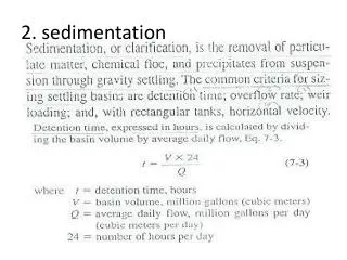
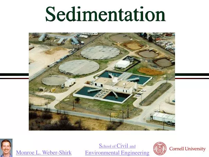
Sedimentation. Simple Sorting. Goal: clean water Source: (contaminated) surface water Solution: separate contaminants from water How?. Where are we?. Unit processes* designed to remove _________________________ remove __________ ___________ inactivate ____________

E N D
Simple Sorting • Goal: clean water • Source: (contaminated) surface water • Solution: separate contaminants from water • How?
Where are we? • Unit processes* designed to • remove _________________________ • remove __________ ___________ • inactivate ____________ • *Unit process: a process that is used in similar ways in many different applications • Unit Processes Designed to Remove Particulate Matter • Screening • Coagulation/flocculation • Sedimentation • Filtration Particles and pathogens dissolved chemicals pathogens Empirical design Theories developed later Smaller particles
Conventional Surface Water Treatment Raw water Filtration Screening sludge sludge Alum Polymers Rapid Mix Disinfection Cl2 Flocculation Storage Sedimentation Distribution sludge
Screening • Removes large solids • logs • branches • rags • fish • Simple process • may incorporate a mechanized trash removal system • Protects pumps and pipes in WTP
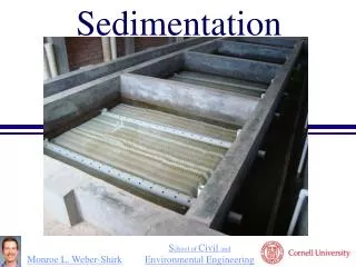
Sedimentation • the oldest form of water treatment • uses gravity to separate particles from water • often follows coagulation and flocculation
Sedimentation: Effect of the particle concentration • Dilute suspensions • Particles act independently • Concentrated suspensions • Particle-particle interactions are significant • Particles may collide and stick together (form flocs) • Particle flocs may settle more quickly • At very high concentrations particle-particle forces may prevent further consolidation
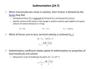
Sedimentation:Particle Terminal Fall Velocity Identify forces projected
Drag Coefficient on a Sphere Stokes Law turbulent boundary laminar turbulent
Floc Drag Flocs created in the water treatment process can have Re exceeding 1 and thus their terminal velocity must be modeled using
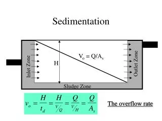
Sedimentation Basin:Critical Path • Horizontal velocity Outlet zone flow rate H Inlet zone Sludge zone WH • Vertical velocity L Sludge out Vc = particle velocity that just barely ______________ gets captured What is Vc for this sedimentation tank?
Sedimentation Basin:Importance of Tank Surface Area Time in tank W H Vc is a property of the sedimentation tank! L Want a _____ Vc, ______ As, _______ H, _______ q. small large small large Suppose water were flowing up through a sedimentation tank. What would be the velocity of a particle that is just barely removed?
long rectangular basins 4-6 hour retention time 3-4 m deep max of 12 m wide max of 48 m long What is Vc for conventional design? Settling zone Outlet zone Inlet zone Sludge zone Sludge out Conventional Sedimentation Basin
Settling zone Outlet zone Inlet zone Sludge zone Design Criteria for Horizontal Flow Sedimentation Tanks • _______________________________ • _______________________________ • _______________________________ • _______________________________ • _______________________________ • Vc of 20 to 60 m/day* • Residence time of 1.5 to 3 hours* Minimal turbulence (inlet baffles) Uniform velocity (small dimensions normal to velocity) No scour of settled particles Slow moving particle collection system Q/As must be small (to capture small particles) * Schulz and Okun And don’t break flocs at inlet!
Sedimentation Tank particle capture • What is the size of the smallest floc that can be reliably captured by a tank with critical velocity of 60 m/day? • We need a measure of real water treatment floc terminal velocities • Research…
Physical Characteristics of Floc: The Floc Density Function • Tambo, N. and Y. Watanabe (1979). "Physical characteristics of flocs--I. The floc density function and aluminum floc." Water Research13(5): 409-419. • Measured floc density based on sedimentation velocity (Our real interest!) • Flocs were prepared from kaolin clay and alum at neutral pH • Floc diameters were measured by projected area
Floc Density Function:Dimensional Analysis! • Floc density is a function of __________ • Make the density dimensionless • Make the floc size dimensionless • Write the functional relationship • After looking at the data conclude that a power law relationship is appropriate floc size
Model Results • For clay assume dclay was 3.5 mm (based on Tambo and Watanabe) • a is 10 and nd is -1.25 (obtained by fitting the dimensionless model to their data) • The coefficient of variation for predicted dimensionless density is • 0.2 for dfloc/dclay of 30 and • 0.7 for dfloc/dclay of 1500 • The model is valid for __________flocs in the size range 0.1 mm to 3 mm clay/alum
Additional Model Limitation • This model is simplistic and doesn’t include • Density of clay • Ratio of alum concentration to clay concentration • Method of floc formation • Data doesn’t justify a more sophisticated model • Are big flocs formed from a few medium sized flocs or directly from many clay particles? • Flocs that are formed from smaller flocs may tend to be less dense than flocs that are formed from accumulation of (alum coated) clay particles
Model Results → Terminal Velocity Q = shape factor (1 for spheres) Requires iterative solution for velocity
Floc Sedimentation Velocity a: 10 nd: -1.25 dclay: 3.5 mm Q: 45/24
Floc density summary • Given a critical velocity for a sedimentation tank (Vc) we can estimate the smallest particles that we will be able to capture • This is turn connects back to flocculator design • We need flocculators that can reliably produce large flocs so the sedimentation tank can remove them
differential sedimentation Flocculation/Sedimentation: Deep vs. Shallow • Compare the expected performance of shallow and deep horizontal flow sedimentation tanks assuming they have the same critical velocity (same Q and same surface area) deeper Expect the _______ tank to perform better! More opportunities to ______ with other particles by _________ ____________ or ________________ collide But the deep tank is expensive to make and hard to get uniform flow! Brownian motion
Flocculation/Sedimentation: Batch vs. Upflow • Compare the expected performance of a batch (bucket) and an upflow clarifier assuming they have the same critical velocity • How could you improve the performance of the batch flocculation/sedimentation tank?
Lamella • Sedimentation tanks are commonly divided into layers of shallow tanks (lamella) • The flow rate can be increased while still obtaining excellent particle removal Lamella decrease distance particle has to fall in order to be removed
Defining critical velocity for plate and tube settlers Path for critical particle? How far must particle settle to reach lower plate? hc L h b a What is total vertical distance that particle will travel? a Vup Va What is net vertical velocity?
Compare times Time to travel distance hc Time to travel distance h =
Comparison with Q/As As is horizontal area over which particles can settle hc L h b a a Vup Va Same answer!
L b a Performance ratio (conventional to plate/tube settlers) • Compare the area on which a particle can be removed • Use a single lamella to simplify the comparison Conventional capture area Plate/tube capture area
Critical Velocity Debate? Schulz and Okun Water Quality and Treatment (1999) WQ&T shows this geometry But has this equation Weber-Shirk Assume that the geometry is
Check the extremes! 90° 45° 10° 5°
Critical Velocity Guidelines • Based on tube settlers • 10 – 30 m/day • Based on Horizontal flow tanks • 20 to 60 m/day • Unclear why horizontal flow tanks have a higher rating than tube settlers • Could be slow adoption of tube settler potential • Could be upflow velocity that prevents particle sedimentation in the zone below the plate settlers http://www.brentwoodprocess.com/tubesystems_main.html Schulz and Okun
Problems with Big Tanks • To approximate plug flow and to avoid short circuiting through a tank the hydraulic radius should be much smaller than the length of the tank • Long pipes work well! • Vc performance of large scale sedimentation tanks is expected to be 3 times less than obtained in laboratory sedimentation tanks* • Plate and tube settlers should have much better flow characteristics than big open horizontal flow sedimentation tanks
Goal of laminar flow to avoid floc resuspension Is Re a design constraint? not a design constraint Re is laminar for typical designs, _____________________
Mysterious Recommendations • Re must be less than 280 (Arboleda, 1983 as referenced in Schulz and Okun) • The entrance region should be discounted due to “possible turbulence” (Yao, 1973 as referenced in Schulz and Okun) But this isn’t about turbulence (see next slide)!!! At a Re of 280 we discard 36 and a typical L/b is 20 so this doesn’t make sense
Entrance Region Length Distance for velocity profile to develop laminar turbulent
Entrance region • The distance required to produce a velocity profile that then remains unchanged • Laminar flow velocity profile is parabolic • Velocity profile begins as uniform flow • Tube and plate settlers are usually not long enough to get to the parabolic velocity profile a
Lamella Design Strategy • Angle is approximately 60° to get solids to slide down the incline • Lamella spacing of 5 cm (b) • L varies between 0.6 and 1.2 m • Vc of 10-30 m/day • Find Vup through active area of tank • Find active area of sed tank • Add area of tank required for angled plates: add L*cos(a) to tank length
Sedimentation tank cross section Effluent Launder (a manifold)
Design starting with Vup • The value of the vertical velocity is important in determining the effectiveness of sludge blankets and thus it may be advantageous to begin with a specified Vup and a specified Vc and then solve for L/b
Equations relating Velocities and geometry Lamella gain Continuity (Lengths are sed tank lengths)
wplate bplate Lplate Qplant Ntanks a Vertical space in the sedimentation tank divided between sludge storage and collection flow distribution Plates flow collection Designing a plate settler
AguaClara Plant Layout (draft) Floc tank Sed tanks Chemical store room Effluent launders Drain Valve access holes Sed tank manifold Steps To the distribution tank
Distributing flow between tanks • Which sedimentation tank will have the highest flow rate? • Where is the greatest head loss in the flow through a sedimentation tank? • Either precisely balance the amount of head loss through each tank • Or add an identical flow restriction in each flow path Where is the highest velocity?
Will the flow be the same? Dh Long K=1 K=1 K=1 K=1 K=0.5 Short K=0.2 Head loss for long route = head loss for short route if KE is ignored Q for long route< Q for short route
Conservative estimate of effects of manifold velocity Control surface 1l long short cs 3 cs 2 cs 4 cs 5 Short orifice Long orifice
This neglects velocity head differences Modeling the flow Since each point can have only one pressure We are assuming that minor losses dominate. It would be easy to add a major loss term (fL/d). The dependence of the friction factor on Q would require iteration.
Design a robust system that gets the same flow through both pipes Add an identical minor head loss to both paths Solve for the control loss coefficient Design the orifice…
Piezometric head decrease in a manifold assuming equal port flows Head loss Kinetic energy Piezometric head decrease in a manifold with n ports d is the manifold diameter represents the head loss coefficient in the manifold at each port or along the manifold as fL/d Note that we aren’t using the total flow in the manifold, we are using Qport
Convert from port to total manifold flow and pressure coefficient Velocity head Loss coefficient Note approximation with f These are losses in the manifold