Download
1 / 15
240 likes | 915 Vues
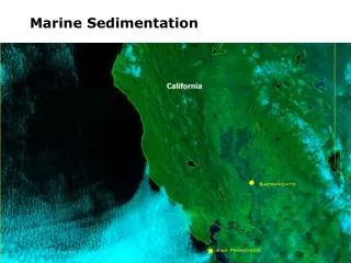
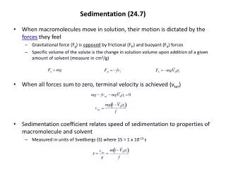
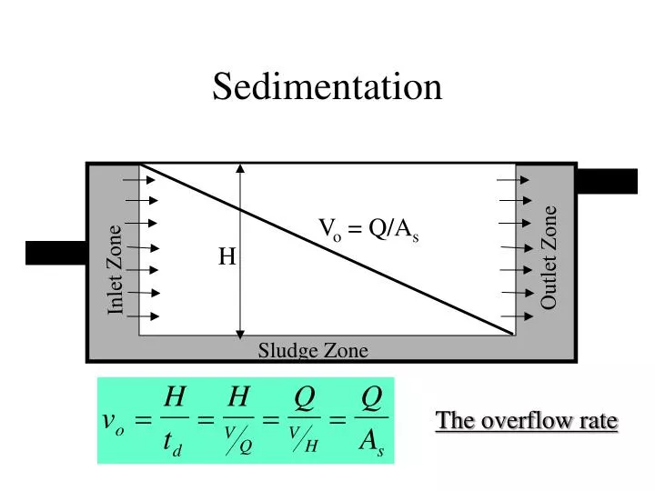
Sedimentation. V o = Q/A s. H. Outlet Zone. Inlet Zone. Sludge Zone. The overflow rate. Sedimentation. Typical design overflow rates for settling tanks are: 500-1000 gpd/ft 2. All particles with a settling velocity greater than or equal to the overflow rate will be 100% removed.

E N D
Sedimentation Vo = Q/As H Outlet Zone Inlet Zone Sludge Zone The overflow rate
Sedimentation Typical design overflow rates for settling tanks are: 500-1000 gpd/ft2 All particles with a settling velocity greater than or equal to the overflow rate will be 100% removed. Particles with a lesser settling velocity will be removed to a fractional extent. Those that happen to enter the settling zone near the bottom will be completely removed and those that enter near the top will not.
Sedimentation Typical design overflow rates for settling tanks are: 500-1000 gpd/ft2 All particles with a settling velocity greater than or equal to the overflow rate will be 100% removed. Particles with a lesser settling velocity will be removed to a fractional extent. Those that happen to enter the settling zone near the bottom will be completely removed and those that enter near the top will not.
Sedimentation Tank Configurations • Rectangular Clarifiers • most common • Circular clarifiers • Center feed • Peripheral feed • Flocculator-Clarifiers
Sedimentation Tank Design • Side water depth: about 12 ft. • settling velocities: 2-6 ft/hr • retention time: 4-8 hr • overflow rates: 500-1000 gpd/ft2 or 0.3-0.7 gpm/ft2 • linear velocities: less than 0.5 ft/min
Sedimentation Tank Design • Side water depth: about 12 ft. • settling velocities: 2-6 ft/hr • retention time: 4-8 hr • overflow rates: 500-1000 gpd/ft2 or 0.3-0.7 gpm/ft2 • linear velocities: less than 0.5 ft/min
Sedimentation Tank Configurations • Rectangular Clarifiers • most common • Circular clarifiers • Center feed • Peripheral feed • Flocculator-Clarifiers
Filtration • A “polishing” solid/liquid separation step • Intended to remove particles • Other impacts • biodegradation • organics adsorption (especially to GAC) • Mn and Fe adsorption
Types of Filtration • Granular media filters • slow sand filters • rapid sand filters • high-rate granular media filters • Membrane filters • microfiltration, ultrafiltration, nanofiltration • Cake filtration • diatomaceous earth
Filtration: Mechanisms • Interception • lines of flow strike media • sedimentation • diffusion • straining • too large to fit between spaces • flocculation • promoted by increased turbulence The transport mechanisms
Filter Design 4.9 m/hr = 2 gpm/ft2 From Tobiason, 1995