Download
1 / 39
410 likes | 885 Vues
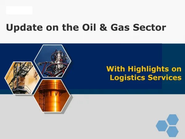
Workshop on Energy Management & Efficiency Improvement in the Oil & Gas Sector. Case Study : Technology Application . November 13, 2009 Hotel Claridges, Aurangzeb Road, New Delhi . By: P.Sur, Executive Director (Operations), Indian Oil Corporation Ltd. Agenda for the Presentation.

E N D
Workshop on Energy Management & Efficiency Improvement in the Oil & Gas Sector Case Study : Technology Application November 13, 2009 Hotel Claridges, Aurangzeb Road, New Delhi By: P.Sur, Executive Director (Operations), Indian Oil Corporation Ltd
Agenda for the Presentation • Energy performance of IOCL Refineries • Major Technologies applied for Energy Conservation • Energy management at Japan • Discussion on some Case Studies: • Flare Gas Recovery System • Foggy Coolers in Gas Turbines • Step less control System in Reciprocating Compressors
Agenda for the Presentation • Energy performance of IOCL Refineries • Major Technologies applied for Energy Conservation • Energy management at Japan • Discussion on some Case Studies: • Flare Gas Recovery System • Foggy Coolers in Gas Turbines • Step less control System in Reciprocating Compressors
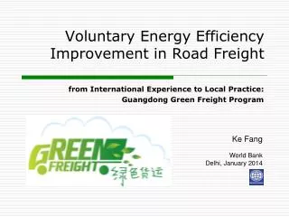
Energy Performance trend of IOCL Refineries w.r.t. Industry Figs in MBTU/ BBL/ NRGF MBN Industry IOCL
Agenda for the Presentation • Energy performance of IOCL Refineries • Major Technologies applied for Energy Conservation • Energy management at Japan • Discussion on some Case Studies: • Flare Gas Recovery System • Foggy Coolers in Gas Turbines • Step less control System in Reciprocating Compressors
Major Technologies Applied in IOCL for Energy Conservation • Modernization of fired heaters. • Provision of APH & OBSG to recover energy from waste heat of furnace flue gases. • Heat exchanger train revamp through Pinch study. • Installation of Gas Turbines with co-generation system in power plants. • Modernisation of Instrumentation and application of Advanced Process Control Strategies. • Flare gas recovery system. • Foggy cooler in Gas turbine. • Step less control system in Reciprocating compressors. • Tank farm automation
Agenda for the Presentation • Energy performance of IOCL Refineries • Major Technologies applied for Energy Conservation • Energy management at Japan • Discussion on some Case Studies: • Flare Gas Recovery System • Foggy Coolers in Gas Turbines • Step less control System in Reciprocating Compressors
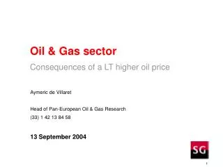
Energy Management at Japan • The trigger • In Japan Primary Energy consumption per GDP is the lowest in the world. In India it is 9.2 times that of Japan. • Japan has to reduce CO2 emission by 14% to honour Kyoto Protocol. • As compared to 1973 position, there is no change in Energy consumption at Industrial Sector, 112% increase in Transportation Sector and 147% increase in Commercial/Residential Sector.
Energy Management at Japan The trigger Primary Energy Consumption per GDP in Japan vs. others China Asia Korea EU
Energy Management at Japan • Energy management Practices at Japan • Factories, which consume total energy of 3000 KL or more per year of crude equivalent is termed as Type 1 designated factory. • Type 1 factory has to employ qualified energy manager (mandatory), no. of which depends on the annual fuel consumption. In case of refineries min. 4 nos. are to be employed. • Submission of periodic reports on energy use. • Top Runner Program: • Introduced in 1999 for Energy Conservation standards for domestic appliances & vehicles. Applicable for total 21 products. • Target has been set for improvement of energy consumption efficiency of these products by 16.4% to 66.1% depending on the product in 2010 with base year of 1995. • In most of the cases target has been achieved in 2005.
Energy Management at Japan • Energy management Practices at Japan • Energy saving labeling system introduced to inform consumers of energy efficiency of home appliances (13 products). • Introduction of Home Energy Management System (HEMS) and Building Energy Management System (BEMS) to control air conditioning and lighting. • Aim is to improve energy consumption efficiency by at least another 30% by 2030.
Energy Management at Japan • Energy management at Japanese Refineries • There are total 34 refineries. All of them are private refinery. • Total crude oil processing capacity is around 225 MMTPA. • No bench mark for Energy Intensity Index is imposed by Govt. But each refinery has to improve it by 1% in each year i.e. cum 5% in 5 years. • M&I of units at 2-4 years interval depending on the type of plant. • APC is extensively used for process control & blending operation
Energy Management at Japan • General guidelines issued for Japanese Refineries on following operational measures • Distillation, Extraction & Absorption • Fired Heaters • Reactors/catalyst regenerators • Heat Exchanger, heating and cooling • Steam and Electrical Power • Rotating Machine and other equipment • Process Instrumentation and Management system • Material loss prevention and others Details Details Details Details Details Details Details Details
Agenda for the Presentation • Energy performance of IOCL Refineries • Major Technologies applied for Energy Conservation • Energy management at Japan • Discussion on some Case Studies: • Flare Gas Recovery System • Foggy Coolers in Gas Turbines • Step less control System in Reciprocating Compressors
Technology application in Energy Conservation- Flare Gas Recovery System Flare Gas Recovery System Implemented in: Mathura, Guwahati , Haldia , BGR Under implementation in: Barauni, Gujarat , Panipat Savings Achieved SRFT/ YrReduction in Flare loss (Kg/ hr) • Mathura: 4500 510 • Guwahati 1460 165 • Haldia 3240 370 • BGR 4800 550
Technology application in Energy Conservation- Flare Gas Recovery System Advantages • Can handle gases • With wide range of mol. wt. • Sweet or corrosive • With occasional liquid slugs • Recovered gas is recycled to Fuel gas System • Can handle fluctuation in Gas Header Pressure in Coker based Refineries.
Technology application in Energy Conservation- Flare Gas Recovery System System Components • The Liquid ring compressor • Mechanical seal flushing system • Separator vessel • Heat exchanger (shell & tube) • By-pass line for 100% circulation
Technology application in Energy Conservation- Flare Gas Recovery System System Description • The liquid Ring compressor takes suction from Downstream of Flare KOD • Compressed gas goes to Fuel Gas System through a separator vessel where the liquid is separated out. • The spill back controller operated on compressor suction pressure. • DM water is used as liquid ring fluid.
Technology application in Energy Conservation- Flare Gas Recovery System System Flow Diagram To FG system Flare Hdr PT Separator Flare KOD Liquid ring Compressor DM water To Flare
Agenda for the Presentation • Energy performance of IOCL Refineries • Major Technologies applied for Energy Conservation • Energy management at Japan • Discussion on some Case Studies: • Flare Gas Recovery System • Foggy Coolers in Gas Turbines • Step less control System in Reciprocating Compressors
Technology application in Energy Conservation- Foggy Cooler in Gas Turbine Foggy coolers in Gas Turbines Implemented in: Mathura Under Implementation in : Gujarat Benefit obtained: Mathura – 1000 SRFT/ yr Estimated befit : Gujarat – 7400 SRFT/ yr
Technology application in Energy Conservation- Foggy Cooler in Gas Turbine Schematic flow Diagram
Technology application in Energy Conservation- Foggy Cooler in Gas Turbine • Mathura Refinery is first refinery in IOCL to implement the concept of installing foggy cooler in GT inlet for better power generation. • To increase the efficiency, it is being installed at the GT’s inlet air duct. • Best fogging device which reduce the combustion air temperature by generating extremely fine (<18 micro metre) water fog at the air duct of the GTG. • Cooling the inlet air increases its density, improving compressor mass flow and thus allowing the turbine to operate at a higher capacity.
Technology application in Energy Conservation- Foggy Cooler in Gas Turbine Working Principle • The foggy cooler works on the principle of evaporative cooling. • Water mist evaporates, taking latent heat of air thus reduces the temp which depend on difference between dry & wet bulb temp.
Agenda for the Presentation • Energy performance of IOCL Refineries • Major Technologies applied for Energy Conservation • Energy management at Japan • Discussion on some Case Studies: • Flare Gas Recovery System • Foggy Coolers in Gas Turbines • Step less control System in Reciprocating Compressors
Technology application in Energy Conservation- Step Less Control in Reciprocating Compressor Implemented in: Guwahati, Barauni, Mathura, Haldia Under Implementation in: Guwahati, Gujarat, Panipat, BGR Savings Achieved SRFT/ Yr Guwahati (HDT MUG) 515 Barauni (CRU & DHDT MUG) 2600 Mathura (OHCU MUG) 1000 Haldia (DHDS RGC) 4500
Technology application in Energy Conservation- Step Less Control in Reciprocating Compressor • Process requirements • To meet process hydrogen demand, the load in the running compressor (s) should be maintained to meet the just requirement of hydrogen as an ideal case. • Reciprocating compressors operate with fixed step loads and thus discharge a fixed quantity of H2 at any load due to availability of just four loading options. • Thus there is always a conditions where amount of hydrogen compressed at available load combination is in excess of what is required by process. • The excess H2 thus compressed, which is not required by the process, is spilled back to the compressor’s suction, thereby wasting substantial amount of energy.
Technology application in Energy Conservation- Step Less Control in Reciprocating Compressor • Working principle • Allows compressor to have step less loading from 0-100%. • Works in the principle of reverse flow regulation. • PLC based computerized system controls the hydraulically operated actuators, installed over the suction valve unloaders. • Hydraulically actuated unloaders keep the suction valves open during part of the compression cycle.
Technology application in Energy Conservation- Step Less Control in Reciprocating Compressor • Working principle (cont..) • A portion of the gas that was taken into the cylinder during the suction cycle is pushed back into the suction line during the compression cycle. • In this way the gas volume per working stroke is controlled. • The system saves compression power at part load, since the energy consumption of a compressor is proportional to the qty of fluid.
Technology application in Energy Conservation- Step Less Control in Reciprocating Compressor • Working principle (cont..) • The power necessary for the operation of the compressor is proportional to the area enclosed by the indicator pressure curve. • The actuators, which have a fast switching solenoid, drive the unloader. The solenoid switches and hydraulic oil flows into the actuator’s hydraulic cylinder forcing the unloader downwards the valve guard. • The Step less control system delays the closing of the suction valve during each compression stroke when the compressor is supposed to run on part load. Thus cylinder pressure follows from C to Cr instead of from C to D.
Technology application in Energy Conservation- Step Less Control in Reciprocating Compressor • Working principle (cont..) • The required power consumption is therefore much lower than at full load. • As the gas flows back from the cylinder chamber into the suction line, the quantity of gas in the cylinder available for compression is reduced. At Cr the solenoid switches, oil flows out of the hydraulic cylinder, the unloader moves upward and the suction valve closes. The compression follows the line from Cr to Dr.
Energy Management at Japan • General guidelines for Japanese Refineries • Distillation, Extraction & Absorption • Optimize reflux ratio • Lower Column pressure • Reduce injection steam • Optimize over flash rate • Reduce solvent ratio • Select energy efficient solvent/ absorbent • Install on stream analyzers • Replace old trays by high performance tray • Change position of feed tray/ draw off tray • Install intermediate cooler or Reboiler • Replace ejector by vacuum pump • Install chiller or heat pump system on O/H condenser • 2 stage condensation of overhead Vapour Back
Energy Management at Japan • General guidelines for Japanese Refineries • Fired Heaters • Reduce Air ratio • Repair damper/register • Install O2 meter • Change or remodel damper • Change draft meter • Control damper remotely • Change or remodel burner • Change heat insulation or refractory • Add convection tubes • Improve velocity profile in convection • Install waste heat Boiler • Install APH • Introduce combustion control • Select or change right auxiliaries like burners, ID/FD etc Back
Energy Management at Japan • General guidelines for Japanese Refineries • Reactors/catalyst regenerators • Optimize Recycle Gas ratio or H2/HC ratio • Lower reactor pressure & optimize Reactor temp • Optimize frequency of catalyst regeneration • Change to high performance catalyst • Maximize heat recovery from reactor effluent • Install hot separator system in HDS unit • Minimize steam/HC ratio in H2 manufacturing unit • Modify CRU to CCRU • High temp regeneration in FCCU, adopt temp resistant catalyst and install regenerator gas expander Back
Energy Management at Japan • General guidelines for Japanese Refineries • Heat Exchanger, heating and cooling • Repair heat insulation • Optimize temp of heated tank • Control run down temp of product • On stream cleaning of heat exchangers • Inject anti-foulant to heat exchangers • Change to high performance HE (Packinox type) • Rearrange HE using Pinch Technology • Heat integration among Process Units Back
Energy Management at Japan • General guidelines for Japanese Refineries • Steam and Electrical Power • Repair heat insulation and steam leakage • Maintain steam trap. Add or change • Lower pressures of SMP & SLP • Maximize condensate recovery • Optimize ejector size, change ejector type or number • Install or add power generator • Install combined cycle co-generation Power Plant Back
Energy Management at Japan • General guidelines for Japanese Refineries • Rotating Machine and other equipment • Maintain machine and equipment • Control no. of operating machines • Control rotating speed of turbines • Cut impeller of pump • Install variable speed device for motor • Install power recovery turbine at HDS unit • Process Instrumentation and Management system • Rationalize business planning (Ex. Production planning) • Streamline manufacturing process • Introduce APC • Integrate various Process units • Introduce computer system for management purpose Back Back
Energy Management at Japan • General guidelines for Japanese Refineries • Material loss prevention and others • Minimize loss from flare stack • Minimize loss at loading and unloading operation • Employ H2 cascading in a series of HDS units • Recover H2 from bleed gas in HDS unit • Rationalize refinery off gas and H2 gas system Back