Download
1 / 31
310 likes | 646 Vues
Production of the LHCb Silicon Tracker Readout Electronics. Outline. Overview of the Readout Electronics 1st preproduction of Digitizer Board Evaluation of performance Integration with LHCb hardware 2nd preproduction Conclusion. LHCb Silicon Tracker principle.

E N D
Production of the LHCb Silicon Tracker Readout Electronics A. Vollhardt, EPF Lausanne/Switzerland
Outline • Overview of the Readout Electronics • 1st preproduction of Digitizer Board • Evaluation of performance • Integration with LHCb hardware • 2nd preproduction • Conclusion A. Vollhardt, EPF Lausanne/Switzerland
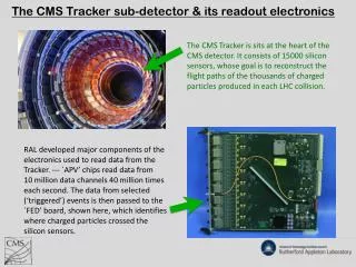
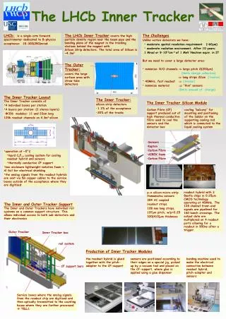
LHCb Silicon Tracker principle • Two distinct tracking systems based on silicon strip detectors, read out via the BEETLE chip • TT: full acceptance angle covered upstream of magnet • IT: only area of highest track densities around beampipe A. Vollhardt, EPF Lausanne/Switzerland
Beetle readout chip • 128 channel charge integrator • polyimide readout hybrid carries 3 (IT) or 4 (TT) Beetle chips for sensors of 384 (IT) or 512 (TT) strips See also: • Talk of F. Lehner: Hybrid Design, Procurement and Testing for the LHCb Silicon Tracker A. Vollhardt, EPF Lausanne/Switzerland
ST Readout electronics A. Vollhardt, EPF Lausanne/Switzerland
low-voltage power Service Box Overview sensor + readouthybrids 5m copper cable Optical fibres for physics data Digitizer Board up to 16 hybrids/boards Digitizer Board Control Card backplane TTC ECS A. Vollhardt, EPF Lausanne/Switzerland
Digitizer Board characteristics • 6 layer PCB, halogen-free, 1.6 mm thickness, symmetric stack • single side mounting, no buried/blind vias • smallest feature size 6 mil, smallest package 0603 • 5 BGA devices: 1x CS49 (0.8 mm pitch), 3-4x BGA144(1.0 mm pitch) • no JTAG chain , no boundary scan • differential traces have controlled impedance/length • standard commercial connectors • NO tuning points • layout optimized for low-cost, high-yield, easy testing 2 versions: Trigger Tracker (4-chip readout), Inner Tracker (3-chip readout) A. Vollhardt, EPF Lausanne/Switzerland
1. Preproduction run • 17 boards produced and electrically tested in late 2004(TT version) • after assembly, all BGAs X-rayed: all solder joints ok! • 2 bugfixes:wrong reference voltage for line receiverAuto-Sync FPGA: shift register one cycle (25ns) too short • all boards except one immediately working:board #10 had ripped via under BGA (fixed) changes for IT version preproduction (and final production): • changed VCSEL biasing • added QPLL RC-network for improved jitter stability A. Vollhardt, EPF Lausanne/Switzerland
Digitizer Board • Power <5 W • Only positive voltages: 2.5 V, 5.0 V A. Vollhardt, EPF Lausanne/Switzerland
Beetle signal at ADC • Flat top 15 nsec wide (of 25 nsec max.) • measured with 5m twisted pair cable • plenty of ‘space’ to set ADC sampling point A. Vollhardt, EPF Lausanne/Switzerland
Linearity A. Vollhardt, EPF Lausanne/Switzerland
Sampling synchronicity I • supply all 16 inputs with ‘synchronous’ testpulse:testpulse generator sourcing 16 LVDS drivers • move sampling time by using TTCrx clock phase shifters (just like in experiment..) • transmit data via GOL+ optical fibres to DACs and scope • record pulseheight of sampled edge vs. programmed delay A. Vollhardt, EPF Lausanne/Switzerland
Sampling synchronicity II A. Vollhardt, EPF Lausanne/Switzerland
GOL VCSEL connection • VCSEL forward voltage with 2.5V anode voltage results in too low GOL current driver voltage level • only 2.5V and 5V available • reduced to 3.3V by low-impedance divider • blocked at VCSEL with 100nF||100pF A. Vollhardt, EPF Lausanne/Switzerland
Eye diagram after 100m • Thanks to Paolo Ciambrone/LHCb Muon A. Vollhardt, EPF Lausanne/Switzerland
Auto-sync Beetle analogue output • Beetle DataValid signal (almost) in parallel to analogue data to frame a triggered event • done via shift register in Actel antifuse FPGA (small version of rad-hard AX54SX32) incl. TMR+ majority voting • Results in at least one IDLE frame per event Beetle DataValid Beetle data after digitization DataValid after 200 ns delay A. Vollhardt, EPF Lausanne/Switzerland
Radiation qualification • Expected radiation levels for Service Box location for 10 years:TID 15 krad, NIEL 2E12 n/cm2 • all commercial devices individually radiation qualified (TID, NIEL and SEE) with proton and neutron irradiation according to LHCb radiation policy • System test: TT Digitizer Board + backplane re-tested in June 2005 with 60 MeV protons to 60 krad (PSI, Switzerland): • analogue test pattern injected • verification of function and performance • no variations in module operation observed A. Vollhardt, EPF Lausanne/Switzerland
Full Readout test A. Vollhardt, EPF Lausanne/Switzerland
Full Readout test • LHCb-style readout (except LHCb Readout Supervisor + CPU farm) A. Vollhardt, EPF Lausanne/Switzerland
Control Card • Under development by Universidade de Santiago de Compostela • Provides TTC signals and slow control interface to each Service Box and its associated frontend electronics • First prototype functional (still being tested) A. Vollhardt, EPF Lausanne/Switzerland
Breaking News: IT version • 10 Digitizer Boards (IT version preproduction) were delivered last Wednesday • initial testing confirm out-of-the-box functionality • important step: re-validate eye diagram with new VCSEL bias! A. Vollhardt, EPF Lausanne/Switzerland
Next steps • detailed testing of IT prototypes: last design verification • launch production order after: • production+assembly time for all boards: ca. 8-10 weeks • all parts available except for VCSELs (LHCb common order placed, expected in November) • ‘bird-food’ supplied by company, special components by us • start setting up test bench during production:basic functionality test (go-nogo)burn-in test (catch infant mortality) A. Vollhardt, EPF Lausanne/Switzerland
Conclusion + Outlook • The preseries production for both versions of the ST Digitizer Board has been completed. • Bugfixes and lessons learned in the TT version were successfully included in the IT version. • Required functionality was verified and system compatibility with common LHCb hardware has been shown. • Preseries hardware is used to form teststands for the TT sensor module production (Zuerich) and the IT sensor production (CERN) • Final qualification pending, design will be released for full production in Q4/05. A. Vollhardt, EPF Lausanne/Switzerland
SPARE SLIDES A. Vollhardt, EPF Lausanne/Switzerland
2.5 V 3x 1 kW differential signal from Beetle Vref (ca. 1 V) Output to GOL serializer 10 kW 39 W Vcm out + 22 W TSA0801 2x 100 nF AD8129 8 bits out - 100 nF 39 W gain: 11 gain: 0.22impedance: 100 Ohm Digitizer Board input stage • Bandwidth: 1.6 kHz (AC-Coupling) to 170 MHz (AD8129) • Amplifier output range matches ADC input range A. Vollhardt, EPF Lausanne/Switzerland
Clock tree A. Vollhardt, EPF Lausanne/Switzerland
TFC distribution • Impedance controlled traces for LVDS signals • TTL traces only used for short (~ 2 cm) for fanning out • equal trace lengths to minimize ch-ch skew A. Vollhardt, EPF Lausanne/Switzerland
Service Box: frame • Fully loaded weight: ca. 10 kg • Power disipation: ca. 150 W (70 W into mixed water cooled heatsink) A. Vollhardt, EPF Lausanne/Switzerland
Service Box cooling • all linear regulators located close to each other • use common copper heatsink (mixed water) to cool all at once • isolate ground slug of regulator package (local ground!) • used for testing: CPU water cooling system: no active cooler, but fan-blown heat-exchanger • Test at full load results in 35 degC case temperature for 25 degC water (=ambient temperature) A. Vollhardt, EPF Lausanne/Switzerland
IT mounting • Service Boxes outside acceptance • Mounted on common IT station frame • ‘5m copper cables’ no not move • cables from Service Box away from detector move (cable chains) A. Vollhardt, EPF Lausanne/Switzerland
TT mounting • Service Boxes mounted outside acceptance to magnet • ‘5m copper cable’ guided in cable chains to station halves • cables away from Service Box fixed in cable trays A. Vollhardt, EPF Lausanne/Switzerland