Download
1 / 8
80 likes | 119 Vues
"The compact oxy.IQ, with its built-in microprocessor, is designed to easily fit into any installation site, whether general purpose or hazardous area. With two-wire loop power, it can be installed right at the sampling point instead of having to be rack or panel mounted.<br><br>The intuitive interface means you can program oxygen analysis on the keypad and display. From selecting and programming desired ranges to performing sensor diagnostics and setting low-reading alarms, this fuel oxygen cell analyzer is smart enough to tell you exactly what you want to know."<br>For More Information visit on our website:- www.instronline.com<br>Our E-mail Address:-info@instronline.com <br>

E N D
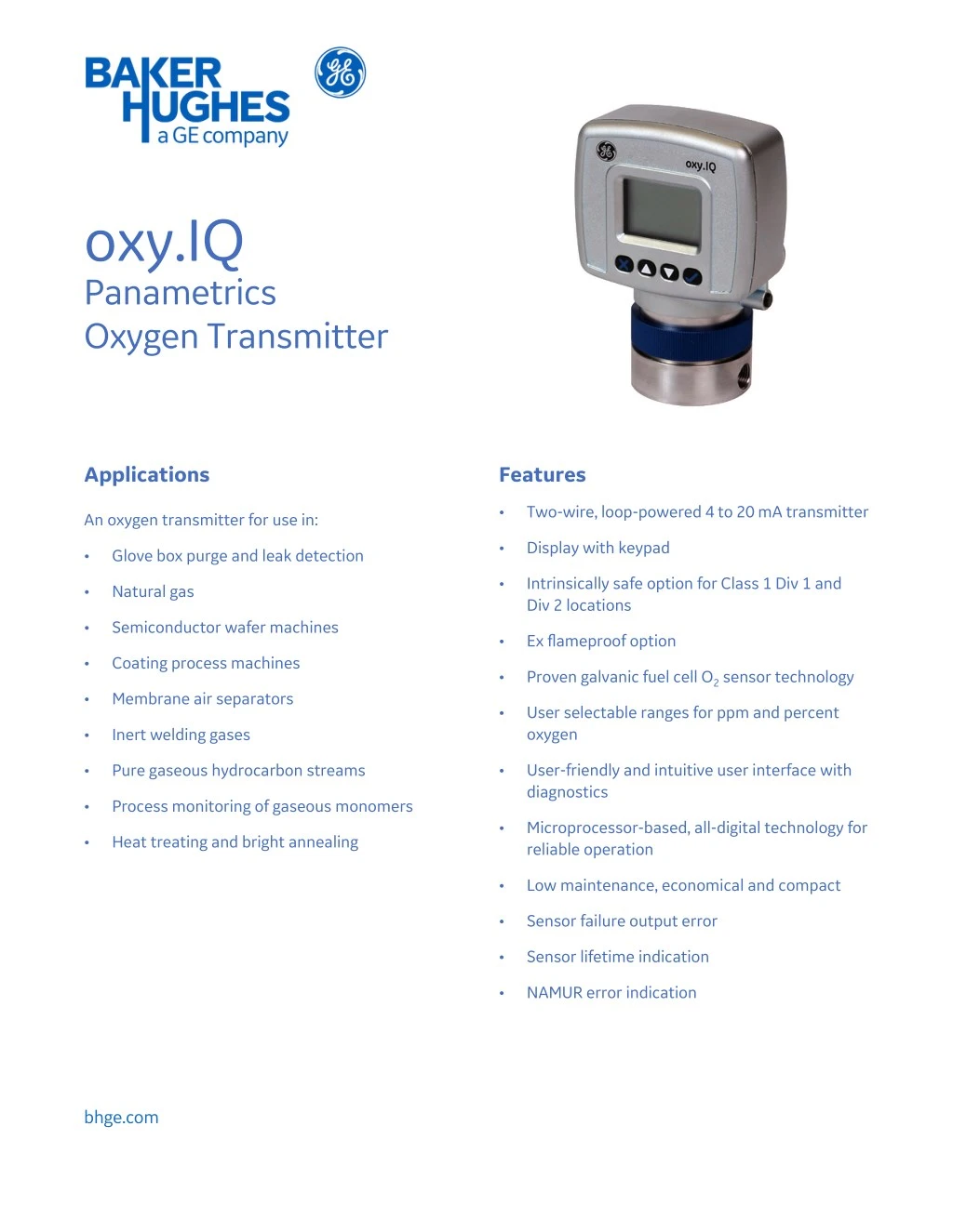
oxy.IQ Panametrics Oxygen Transmitter Applications Features • Two-wire, loop-powered 4 to 20 mA transmitter An oxygen transmitter for use in: • Display with keypad • Glove box purge and leak detection • Intrinsically safe option for Class 1 Div 1 and Div 2 locations • Natural gas • Semiconductor wafer machines • Ex flameproof option • Coating process machines • Proven galvanic fuel cell O2 sensor technology • Membrane air separators • User selectable ranges for ppm and percent oxygen • Inert welding gases • User-friendly and intuitive user interface with diagnostics • Pure gaseous hydrocarbon streams • Process monitoring of gaseous monomers • Microprocessor-based, all-digital technology for reliable operation • Heat treating and bright annealing • Low maintenance, economical and compact • Sensor failure output error • Sensor lifetime indication • NAMUR error indication bhge.com
Panametrics Oxygen Transmitter Control at the Tip of a Finger The oxy.IQ is a highly reliable and cost-effective two-wire, loop-powered transmitter with a linearized 4 to 20 mA output. It measures oxygen in ten ppm ranges and seven percentage ranges. All ranges are user- selectable. This compact transmitter uses proven sensor technology to accurately measure O2 in a variety of gases, even in hazardous environments. The rugged oxy.IQ is controlled by a microprocessor that enables the user to select the range, trim outputs and perform calibration. Improved user interface includes user-selectable and programmable ranges, sensor diagnostics including a sensor lifetime feature and sensor raw signal, low reading/sensor failure signal and temperature compensation. Programming is easily done using the keypad and display. These keypad buttons allow complete functionality in hazardous areas when equipped with a zener barrier or a galvanic isolator per drawing 752-347. Proven Sensor Technology The oxy.IQ’s oxygen sensor is an advanced galvanic fuel cell that provides superior performance, accuracy, stability and long life. The cell’s innovative design eliminates the potential for negative signal output, reduces sources of contamination. Installation Flexibility The compact oxy.IQ, with its built-in microprocessor, is designed to fit easily into any installation site. The oxy.IQ can be installed right at the sampling point, whereas other transmitters must be rack or panel mounted. The cell is unaffected by other background gases or hydrocarbons and is compatible with acid gases (OX-2 and OX-4 cells). Recovery from air at low ppm levels takes just a few minutes. Because the cell is self-contained, minimal maintenance is required. There is no electrolyte to change or electrodes to clean. Sample Systems In addition to standard features and options, GE offers a full line of sample handling systems for a variety of applications. If needed, GE can design and build a sample conditioning system to meet unique application requirements. Please contact GE for details. Intrinsically Safe When equipped with optional zener barriers or a galvanic isolator, the oxy.IQ can be mounted in a hazardous (classified) location. Oxygen Sensor Interference Gases Gas OX-1 and OX- 5, ppm Cont. OX-2, ppm Cont. OX-3, % OX-4% Cont. Int. (1) Cont. Int. H2S <5 ppm <10 ppm 0.0005% 0.01% 0.001% 0.1% SO3 <10 ppm <10 ppm 0.01% 0.1% 0.01% 0.1% SO2 <10 ppm (3) 0.01% 0.1% (3) (3) HCI <1000 ppm (3) 0.1% 1.0% (3) (3) HCN <1000 ppm (3) 0.1% 1.0% (3) (3) CO2 <1000 ppm (3) 0.1% 20% (3) (3) Advanced Galvanic Fuel Cell Sensor NO2 (2) (2) (2) (2) (2) (2) CL2 (2) (2) (2) (2) (2) (2) Cont. = Continuous, Int. = Intermittent (1) Recommended maximum exposure 30 minutes followed by flushing with ambient air for equal period (2) Minimal effect on sensor performance, but produces signal interference of 1:2 ratio, ppm levels only. For example, 100 ppm NO2 looks like 200 ppm O2 (3) Minimal effect on sensor performance
oxy.IQ Specifications Intrinsically Safe (IS) Installation Intrinsically safe installations require a zener barrier, one IS cable and one non-IS cable. All Installations Process Wetted Materials • SS process unit: 316 stainless steel, Viton® O-ring, gold plated sensor electrical contacts and glass Power Requirements 24 to 28 VDC at 50 mA User-Selectable Measurement Ranges • PPM sensors: – 0 to 10 ppmv O2 (OX-1 or OX-2 only) – 0 to 20 ppmv O2 (OX-1 or OX-2 only) – 0 to 50 ppmv O2 (OX-1 or OX-2 only) – 0 to 100 ppmv O2 – 0 to 200 ppmv O2 – 0 to 500 ppmv O2 – 0 to 1000 ppmv O2 – 0 to 2000 ppmv O2 – 0 to 5000 ppmv O2 – 0 to 10,000 ppmv O2 • Percent sensors: – 0% to 1% O2 – 0% to 2% O2 – 0% to 5% O2 – 0% to 10% O2 – 0% to 25% O2 – 0% to 50% O2 Cable • PN 704-1318: blue jacket, twisted pair with connector; 26 AWG; 2 or 10 m length Output Total load must equal 250 W ±5% when using zener barrier General Purpose and Non-Incendive (Div 2) Installations Standard option package or IS package, no Zener barrier or galvanic isolator is required. Power Requirements 9 to 28 VDC loop powered, 0.7 W maximum Cable • PN 704-1317: black jacket, twisted pair with connector; 26 AWG; 2 or 10 m length
oxy.IQ Specifications All Installations Dimensions 4.10 x 2.75 x 2.05 in. (104.1 x 69.9 x 52.1 mm) Accuracy • ±1% of range at calibration point • ±2% of range at the calibration point for the 0 to 10 ppmv range (OX-1 or OX-2 only) Weight 1.35 lb (612 grams) Sample Flow Rate 1.0 SCFH (500 cc/min) recommended for process units Repeatability • ±1% of range • ±2% of Range for the 0 to 10 ppmv range (OX-1, 2 only) Electrical Classification/Certification Intrinsically Safe USA/Canada IS for Class I, Div 1, Groups ABCD, T4 AEx ia IIC T4 ATEX and IECEx Ex ia IIC Ga T4 Tamb -20 to 60°C IS package, non-incendive without use of Zener barrier or galvanic isolator: • USA/Canada: Class 1, Div 2, Groups A, B, C, D; T4 • ATEX/IECEx: Ex na IIC T4 Resolution ±0.1% of range Linearity ±2% of range (OX-1, 2, 3, 5) ±5% of range (OX-4) O2 Sensor Operating Temperature 32 to 113°F (0 to 45°C) European Compliance Complies with EMC Directive 2004/108/EC Sample Pressure Vented to atmosphere during operation and calibration Atmospheric Pressure Effect ±0.13% of reading per mmHg (directly proportional to absolute pressure). During calibration, pressure and flow must be kept constant. Process Connection • 1/8 in. NPT inlet and outlet
Dimensions 2.05 [52.1] 1.58 [40.1] 2.75 [69.9] 4.10 [104.1] .30 [7.7] 1.33 [33.8] 1.03 [26.2] 1/8-27NPT-2B 2 X 8-32 UNF-2B 2 X 1.00 [25.4] Note: all dimensions are inches [mm] Ø1.75 [44.5]
Installation Options Hazardous Location Non-Hazardous Location POWER SUPPLY ZBB BUS BAR BROWN RED 3 +24V 1 4 2 GREEN BLUE 24V RETURN GREEN BLACK oxy.IQ Transmitter MTL7706 IS GROUND 4-20MA ANALOG INPUT DEVICE IS Cable 704-1318-xx (Blue Jacket) Non-IS Cable R1 1. Equipment connected to barrier inputs must not use or generate more than 250V. 2. Total load of R1 + R2 must equal 250 ohms ±5%. BLACK R2 Hazardous Location Non-Hazardous Location POWER SUPPLY Class 1 Div 2 Enclosure BLUE +24V 24V RETURN oxy.IQ Transmitter BROWN BROWN 4-20MA ANALOG INPUT DEVICE 704-1317-xx (Black Jacket) Maximum load of analog input device is dependent on power supply voltage and cable resistance. 1. For Class 1 Div 2 installation, the oxy.IQ shall be installed in an appropriately rated final enclosure accepting a Division 2 wiring method per NEC/CEC. Non-Hazardous Location POWER SUPPLY BLUE +24V 24V RETURN oxy.IQ Transmitter BROWN BROWN 4-20MA ANALOG INPUT DEVICE 704-1317-xx (Black Jacket) Maximum load of analog input device is dependent on power supply voltage and cable resistance.
Ordering Information Record selected option in blank spaces indicated at bottom of form. OXY.IQ-BCD-E Option Code A - Model Only oxy.IQ Oxygen Transmitter; 4 to 20 mA output B - Sensor 0 No sensor 1 Standard ppm, 0 to 10, 20, 50, 100, 200, 500, 1000 ppm 2 Acid ppm, 0 to 10, 20, 50, 100, 200, 500, 1000 ppm 3 Standard percent sensor 4 Acid percent sensor 5 Standard ppm, 0 to 100, 200, 500 and 1000 ppm C - Package 1 Standard 3 Intrinsically safe (US/CAN Class 1 Div 1) or Non-incendive (US/CAN Class 1 Div 2) 4 Ex flameproof D - Cable Length 0 No cable 1 2 meter cable 2 10 meter cable E - Zener Barrier 0 None 1 Zener barrier 2 Galvanic isolator Note: For Class 1 Div 1, either zener barrier or galvanic isolator must be selected. For Class 1 Div 2, no barriers needed. Please refer to dwg 752-347 for installation guidelines. __ – __ ___ ___ ___ [Use this number to order product]
bhge.com © 2017 Baker Hughes, a GE company – All rights reserved. Baker Hughes reserves the right to make changes in specifications and features shown herein, or discontinue the product described at any time without notice or obligation. Contact your BHGE representative for the most current information. The Baker Hughes logo is a trade mark of Baker Hughes, a GE company. The GE Monogram is a trademark of the General Electric Company. 920-603D