Download
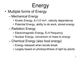
1 / 38
380 likes | 550 Vues
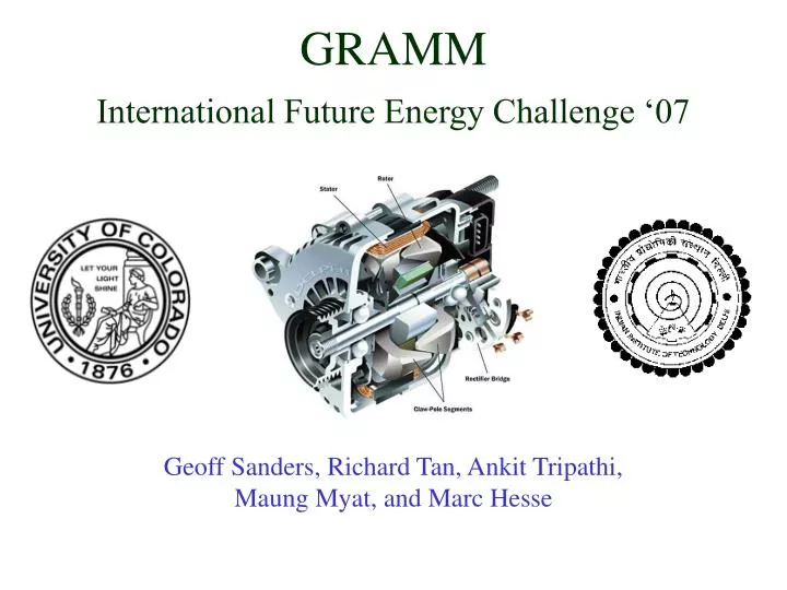
GRAMM International Future Energy Challenge ‘07. Geoff Sanders, Richard Tan, Ankit Tripathi, Maung Myat, and Marc Hesse. Overview. Purpose & Specifications System Description Electric Machine Power Converter Controller Circuit In-circuit Debugger Other parts and purchases

E N D
GRAMMInternational Future Energy Challenge ‘07 Geoff Sanders, Richard Tan, Ankit Tripathi, Maung Myat, and Marc Hesse
Overview Purpose & Specifications System Description Electric Machine Power Converter Controller Circuit In-circuit Debugger Other parts and purchases Updated Labor Distribution Updated detailed schedule Questions/Suggestions and Comments
Purpose & Specifications Electric machine (motor): Works both as a starter (motoring) and an alternator (generator) Must provide 30 Nm of Torque startup. Must motor up to 3000 rpm in 3-5 seconds Must generate 1 KW of power Must be at least 75% efficient Must use NEMA frame 56 Target: Hybrid Electric Car Reasons: IFEC ’07 challenge Save Space Decrease Cost Increase Efficiency
System Description Starter-Alternator Unit (motor) Pole Changing, ‘N’ winding reduction, Flux based design Power Converter Power Board (STEVAL-IHM009V1) Inverter/Rectifier Generator exciter System Controller Control Board (STEVAL-IHM001V1) Chip (ST7FMC2) Gate Drivers (MOSFET DRIVER) User Interface (On-Off switch, emergency switch) Indart series debugging board (INDART-STX/D) ST7 Debugger Program Control panel software (AK-ST7FMC)
Test Set-Up dynamometer (drive and brake) belt drive coupling machine power feeders system controller dyno control electric machine (NEMA 56) power converter torque measurement shaft position measurement PC 200 VDC
Electric Machine Hardware • Received free 3-phase ¾ hp squirrel cage induction machine • Measured parameters and weight • Determined that the slot count is 36 (we need 24 slots) • Allowed us to specify the exact machine we need • Baldor M3155 3-phase squirrel cage induction machine • 2 hp (1.49 kW) • 3450 rpm, 2 pole • 24 slots, 12.4 in. long, 6.8 A max • NEMA 56 frame • Will test, then re-wind machine for 8-4 pole configuration
Characteristic 1 (8-pole) Starting ~ 27Hz, Torque ~ 36Nm f->50Hz, speed -> 750rpm Switch to 4-pole operation Characteristic 2 (4-pole) f->50Hz, speed -> 1500rpm Characteristic 3 (4-pole) f->75Hz, speed -> 2250rpm N reduction (N/2) f->100Hz, speed -> 3000rpm Characteristic 4 (4-pole) Speed=3000rpm Generating 4500 GENERATION MOTORING II I 4000 operating point 3 3500 characteristic 4 3000 2500 characteristic 3 speed[rpm] 2000 characteristic 2 1500 characteristic 1 1000 500 starting characteristic at 27.5 Hz and 24Aline peak by increasing flux 0 -30 -20 -10 0 10 20 30 40 Torque [Nm] Torque-Speed Characteristics of Machine • Torque curves for each characteristic V E/f = 4.44 * N * T = (/2) * (pole/2)* * Fmr * sin r
8 Pole Winding Configuration and MMF • 8-pole configuration • Nrat turns per phase • winding connection
4 Pole Winding Configuration and MMF • 4-pole configuration • Nrat turns per phase • Y-Y winding connection
4-pole configuration • Nrat /2turns per phase • Y-Y winding connection Winding Switching
Power Converter Board • AC Induction Motor ControlPower board SEMITOP®3 3kW(STEVAL-IHM009V1)
Power Converter:Block Diagram 200V Power Supply Control Board HV Monitoring Power Regulation Three Phase Inverter (STG3P3M25N60) PWM Input AC Induction Machine BEMF Temperature Sensor Tachometer Brake Motor
STG3P3M25N603 Phase inverterIGBT - SEMITOP®3 module • General features • N-channel very fast PowerMESH™ IGBT • Lower on-voltage drop (Vcesat) • Lower CRES / CIES ratio (no cross-conduction • susceptibility) • Very soft ultra fast recovery anti-parallel diode • High frequency operation up to 70 KHz • New generation products with tighter • Parameter distribution • One screw mounting • Compact design • Semitop®3 is a trademark of Semikron
VIPer12ADIP - ELow Power OFF-Line SMPS Primary Switcher • Description • The VIPer12A combines a dedicated current mode PWM controller with a high voltage Power MOSFET on the same silicon chip. • The internal control circuit offers the following benefits: • Large input voltage range on the VDD pin accommodates changes in auxiliary supply voltage. • This feature is well adapted to battery charger adapter configurations. • Automatic burst mode in low load condition. • Over-voltage protection in HICCUP mode. • Features • Fixed 60kHZ Switching Frequency • 9V to 38V Wide Range VDD Voltage • Current Mode Control • Auxiliary Under-voltage Lockout with Hysteresis • High Voltage Start-up Current Source • Over-temperature, Over-current and • Over-voltage Protection with Auto-Restart
L78L05ACZPOSITIVE VOLTAGE REGULATOR • OUTPUT CURRENT UP TO 100 mA • OUTPUT VOLTAGE OF 5V • THERMAL OVERLOAD PROTECTION • SHORT CIRCUIT PROTECTION • NO EXTERNAL COMPONENTS ARE REQUIRED • AVAILABLE IN EITHER ±5% (AC) OR ±10% (C) SELECTION
Silicon Avalanche Diodes (P6KE Series)600 Watt Axial Leaded Transient Voltage Suppressors • FEATURES • RoHS Compliant • 6.8 to 550 Volts • Uni-directional and Bi-directional • Glass passivated chip junction in DO-15 Package • 600W surge capability at 10/1000μs wave form • Excellent clamping capability • Low zener impedance • Fast response time: typically less than 1.0ps from 0 Volts to BV min. • Typical IR less than 1μA above 10V
System controller Board • AC Induction Motor ControlControl BoardSTEVAL-IHM001V1
System Controller:Block Diagram Potentiometers ST7FMC2 ICC Interface A/D Converters PWM Generator Debug Board ICC Connector Bridge Drivers (L6386) Power Board SPI Interface SPI EEPROM(M95040) Feedback Switches 16 KB FLASH Memory 768 Bytes RAM LEDs 16 MHz Oscillator
MCMP0 Register Phase U Preload Register Phase V Preload Register Phase W Preload Register Phase U Waveform Phase V Waveform Phase W Waveform PWM Timing
Idle Start Run Stop Brake Wait Fault System Controller Flowchart Initialize Peripherals Main Loop Interrupts Check State Event U Reload PWM Duty Cycle Emergency Stop Stop Motor Send System Data (RS232) Event R or Z ART Reset Update Counters Update LEDs Event C or D Tachometry SCI Send Data Check for Errors External
User Interface/Debugger Testing the Control/Power board
Why use inDart-STX? • Real time code execution without Probes • In-Circuit debugging • Hardware and software testing in real time • Built in FLASH programmer (Data Blaze Programming utility) • Visual Debug user interface (with integrated C compiler and assembler and source level symbolic debugging) • Hardware self diagnostic test • Working frequency as high as the microcontroller itself • Allows for programming the content of FLASH when chip already is in the circuit • Uses ICC (In circuit communication to interface the programming tool like inDART) with the microcontroller we have
User Interface/Debugger inDart-STX
PC Interface Controller Control panel software (AK-ST7FMC)
Safety Face shield Safety shield
Distribution of Work • Geoff • Custom Motor • Programming the micro-controller • Richard • Custom Motor • Calculation and simulation with the actual motor parameters • Maung • Custom Motor • PCB layout for the 64 pins controller • Ankit • Custom Motor • Permanent motor design/ Programming the micro-controller • Marc • Programming the micro-controller • Documentation
Milestone 1 • Test system using regular induction machine • With 64 pin controller board (1st revision) • Should work the same as purchased 44 pin controller board • Custom machine nearly finished • Switching circuit complete (wire wrap)
Milestone 2 • Complete system test with: • Custom machine finished • Completed switching circuit PCB • Pole changing ability confirmed
Final Open-Lab Expo • Complete closed-loop operation of: • Custom pole changing induction machine implementing N reduction • Meeting the basic IFEC requirements • Documentation complete
Questions / Comments Thank you! http://www.smartquestion.com/images/sq_image.jpg