Download
1 / 32
320 likes | 661 Vues
Extracted from The Electricians Guide Fifth Edition. by John Whitfield ... Extracted from The Electricians Guide Fifth Edition. by John Whitfield. Published by EPA ...

E N D
KF 1063 LECTURE 13 KF1063 Pengenalan Kejuruteraan Elektrik, ®mbi, hafizah
CONTENTS • Circuit Interference • EMC • RFI • EMI • Methods of Avoiding Circuit Interference • Noise KF1063 Pengenalan Kejuruteraan Elektrik, ®mbi, hafizah
INTRODUCTION • Electromagnetic Compatibility – EMC : The ability of a product coexist in its electromagnetic environment without causing or suffering functional degradation or damage • Emissions: propagation of electromagnetic interference (EMI) from noncompliant devices and in particular radiated and conducted radio frequency interference (RF) • Susceptibility: The detrimental effects on susceptible devices (victims) of EMI in forms that include electrostatic discharge (ESD) and other forms of electrical overstress (EOS) • EMC Regulatory: • North American – FCC (Federal Communication Commission, US) & DOC (Department of Communication, Canada ) • Worldwide — IEC (International Electrotechnical Commission) • European Union: IEC and CISPR (International Special Committee on Radio Interference) KF1063 Pengenalan Kejuruteraan Elektrik, ®mbi, hafizah
EMC KF1063 Pengenalan Kejuruteraan Elektrik, ®mbi, hafizah
EMI • Electromagnetic Interference, EMI : A process by which disruptive electromagnetic energy is transmitted from one electromagnetic device to another via radiated or conducted paths (or both). • EMI can propagate by two means: • By radiation - where the energy can be coupled either through magnetic or electric field or as an electro-magnetic wave between the source and the victim. • By conduction - where the EMI energy will propagate along power supply cable and the power source. • EMI sources: • Rectifying diodes • Switching components (IGBTs) • High frequency transformers and chokes • Circuit layouts (high dv/dt long wires, high dv/dt wide loops, high current wires) • Mechanical switches bouncing KF1063 Pengenalan Kejuruteraan Elektrik, ®mbi, hafizah
EMI KF1063 Pengenalan Kejuruteraan Elektrik, ®mbi, hafizah
RFI • Radio Frequency Interference, RFI : Electromagnetic radiation which is emitted by electrical circuits carrying rapidly changing signals, as a by-product of their normal operation, and which causes unwanted signals (interference or noise) to be induced in other circuits • Radio Frequency Interference (RFI) is considered as part of the EMI spectrum, with interference signals being within the radio frequency (RF) range. This term was once used interchangeably with EMI. KF1063 Pengenalan Kejuruteraan Elektrik, ®mbi, hafizah
EMI/RFI KF1063 Pengenalan Kejuruteraan Elektrik, ®mbi, hafizah
EMI/STANDARD KF1063 Pengenalan Kejuruteraan Elektrik, ®mbi, hafizah
PROTECTION Shielding Ferrite Core Main Filters KF1063 Pengenalan Kejuruteraan Elektrik, ®mbi, hafizah
EMI/RFI PROTECTION • Physical Isolation: Devices that emit electromagnetic radiation should be kept a reasonable distance from your PC, peripherals and media. This includes television sets, radios, lights, kitchen appliances, and stereo speakers (the ones designed for use with PCs are generally shielded and are much less of an issue). • Use Dedicated Circuits: Many office buildings especially, have separate power circuits that are intended for use by PCs. Keeping your PC on a circuit that is separate from the circuit running your refrigerator and air conditioning unit means that there will be much less interference passing to the computer from the other devices (and this will also improve the quality of the power being sent to your machine in general). • Power Conditioning: The use of a line conditioner or uninterruptible power supply can filter out interference caused by other devices that share a line with your PC. KF1063 Pengenalan Kejuruteraan Elektrik, ®mbi, hafizah
INTERFERENCE KF1063 Pengenalan Kejuruteraan Elektrik, ®mbi, hafizah
EMI/RFI KF1063 Pengenalan Kejuruteraan Elektrik, ®mbi, hafizah
EMI/RFI KF1063 Pengenalan Kejuruteraan Elektrik, ®mbi, hafizah
EMI/RFI KF1063 Pengenalan Kejuruteraan Elektrik, ®mbi, hafizah
EMI/RFI KF1063 Pengenalan Kejuruteraan Elektrik, ®mbi, hafizah
EMI/RFI KF1063 Pengenalan Kejuruteraan Elektrik, ®mbi, hafizah
EMI/RFI KF1063 Pengenalan Kejuruteraan Elektrik, ®mbi, hafizah
EMI/RFI KF1063 Pengenalan Kejuruteraan Elektrik, ®mbi, hafizah
to the 16th Edition IEE Regulations to the 16th Edition IEE Regulations Fig 5.1 - Three-phase delta/star transformer showing earthing arrangements Fig 5.1 - Three-phase delta/star transformer showing earthing arrangements Earthing Earthing chapter 7Special Installations chapter 7Special Installations chapter 1The IEE Regulations chapter 1The IEE Regulations chapter 8Testingand Inspection chapter 4Cables, Conduitsand Trunking chapter 4Cables, Conduitsand Trunking chapter 8Testingand Inspection chapter 2Installation Requirements and Characteristics chapter 2Installation Requirements and Characteristics chapter 3Installation Controland Protection chapter 3Installation Controland Protection 5.1 - The earthing principle 5.1 - The earthing principle 5.6 - Protective multiple earthing (PME) 5.6 - Protective multiple earthing (PME) 5.2 - Earthing Systems 5.2 - Earthing Systems 5.7 - Earthed concentric wiring 5.7 - Earthed concentric wiring 5.3 - Earth fault loop impedance 5.3 - Earth fault loop impedance 5.8 - Other protection methods 5.8 - Other protection methods 5.4 - Protective conductors 5.4 - Protective conductors 5.9 - Residual current devices (RCDs) 5.9 - Residual current devices (RCDs) 5.5 - Earth electrodes 5.5 - Earth electrodes 5.10 - Combined functional and protective---------earthing 5.10 - Combined functional and protective---------earthing 5.1.1 - What is earthing? 5.1.1 - What is earthing? chapter 5Earthing chapter 5Earthing 5.1.2 - The advantages of earthing 5.1.2 - The advantages of earthing 5.1.3 - The disadvantages of earthing 5.1.3 - The disadvantages of earthing 5.1.1 - What is earthing? The whole of the world may be considered as a vast conductor which is at reference (zero) potential. In the UK we refer to this as 'earth' whilst in the USA it is called 'ground'. People are usually more or less in contact with earth, so if other parts which are open to touch become charged at a different voltage from earth a shock hazard exists (see {3.4}). The process of earthing is to connect all these parts which could become charged to the general mass of earth, to provide a path for fault currents and to hold the parts as close as possible to earth potential. In simple theory this will prevent a potential difference between earth and earthed parts, as well as permitting the flow of fault current which will cause the operation of the protective systems. The standard method of tying the electrical supply system to earth is to make a direct connection between the two. This is usually carried out at the supply transformer, where the neutral conductor (often the star point of a three-phase supply) is connected to earth using an earth electrode or the metal sheath and armouring of a buried cable. {Figure 5.1} shows such a connection. Lightning conductor systems must be bonded to the installation earth with a conductor no larger in cross-sectional area than that of the earthing conductor. 5.1.1 - What is earthing? The whole of the world may be considered as a vast conductor which is at reference (zero) potential. In the UK we refer to this as 'earth' whilst in the USA it is called 'ground'. People are usually more or less in contact with earth, so if other parts which are open to touch become charged at a different voltage from earth a shock hazard exists (see {3.4}). The process of earthing is to connect all these parts which could become charged to the general mass of earth, to provide a path for fault currents and to hold the parts as close as possible to earth potential. In simple theory this will prevent a potential difference between earth and earthed parts, as well as permitting the flow of fault current which will cause the operation of the protective systems. The standard method of tying the electrical supply system to earth is to make a direct connection between the two. This is usually carried out at the supply transformer, where the neutral conductor (often the star point of a three-phase supply) is connected to earth using an earth electrode or the metal sheath and armouring of a buried cable. {Figure 5.1} shows such a connection. Lightning conductor systems must be bonded to the installation earth with a conductor no larger in cross-sectional area than that of the earthing conductor. Return to top of pageExtracted from The Electricians Guide Fifth Editionby John WhitfieldPublished by EPA Press Click Here to order your Copy Click here for list of abbreviations Return to top of pageExtracted from The Electricians Guide Fifth Editionby John WhitfieldPublished by EPA Press Click Here to order your Copy Click here for list of abbreviations chapter 6Circuits chapter 6Circuits chapter 9Data cablingand Networks chapter 9Data cablingand Networks Contents Contents SIGNAL AND NOISE • Isyarat (Signal) merupakan apa yang diukur dari punca bekalan isyarat sementara Hingar (Noise) pula merupakan maklumat tambahan yang boleh menggangu dan mengubah sesuatu isyarat. • Hingar bersifat ketaktentuan dan rawak serta tidak boleh dihapuskan (eliminate) tetapi boleh diminimumkan. • Memandangkan hingar tidak boleh dihapuskan, maka biasanya Nisbah Isyarat-ke-Hingar (SNR) sering diambil kira. KF1063 Pengenalan Kejuruteraan Elektrik, ®mbi, hafizah
to the 16th Edition IEE Regulations to the 16th Edition IEE Regulations Fig 5.1 - Three-phase delta/star transformer showing earthing arrangements Fig 5.1 - Three-phase delta/star transformer showing earthing arrangements Earthing Earthing chapter 7Special Installations chapter 7Special Installations chapter 1The IEE Regulations chapter 1The IEE Regulations chapter 4Cables, Conduitsand Trunking chapter 8Testingand Inspection chapter 8Testingand Inspection chapter 4Cables, Conduitsand Trunking chapter 2Installation Requirements and Characteristics chapter 2Installation Requirements and Characteristics chapter 3Installation Controland Protection chapter 3Installation Controland Protection 5.1 - The earthing principle 5.1 - The earthing principle 5.6 - Protective multiple earthing (PME) 5.6 - Protective multiple earthing (PME) 5.2 - Earthing Systems 5.2 - Earthing Systems 5.7 - Earthed concentric wiring 5.7 - Earthed concentric wiring 5.3 - Earth fault loop impedance 5.3 - Earth fault loop impedance 5.8 - Other protection methods 5.8 - Other protection methods 5.4 - Protective conductors 5.4 - Protective conductors 5.9 - Residual current devices (RCDs) 5.9 - Residual current devices (RCDs) 5.5 - Earth electrodes 5.5 - Earth electrodes 5.10 - Combined functional and protective---------earthing 5.10 - Combined functional and protective---------earthing 5.1.1 - What is earthing? 5.1.1 - What is earthing? chapter 5Earthing chapter 5Earthing 5.1.2 - The advantages of earthing 5.1.2 - The advantages of earthing 5.1.3 - The disadvantages of earthing 5.1.3 - The disadvantages of earthing 5.1.1 - What is earthing? The whole of the world may be considered as a vast conductor which is at reference (zero) potential. In the UK we refer to this as 'earth' whilst in the USA it is called 'ground'. People are usually more or less in contact with earth, so if other parts which are open to touch become charged at a different voltage from earth a shock hazard exists (see {3.4}). The process of earthing is to connect all these parts which could become charged to the general mass of earth, to provide a path for fault currents and to hold the parts as close as possible to earth potential. In simple theory this will prevent a potential difference between earth and earthed parts, as well as permitting the flow of fault current which will cause the operation of the protective systems. The standard method of tying the electrical supply system to earth is to make a direct connection between the two. This is usually carried out at the supply transformer, where the neutral conductor (often the star point of a three-phase supply) is connected to earth using an earth electrode or the metal sheath and armouring of a buried cable. {Figure 5.1} shows such a connection. Lightning conductor systems must be bonded to the installation earth with a conductor no larger in cross-sectional area than that of the earthing conductor. 5.1.1 - What is earthing? The whole of the world may be considered as a vast conductor which is at reference (zero) potential. In the UK we refer to this as 'earth' whilst in the USA it is called 'ground'. People are usually more or less in contact with earth, so if other parts which are open to touch become charged at a different voltage from earth a shock hazard exists (see {3.4}). The process of earthing is to connect all these parts which could become charged to the general mass of earth, to provide a path for fault currents and to hold the parts as close as possible to earth potential. In simple theory this will prevent a potential difference between earth and earthed parts, as well as permitting the flow of fault current which will cause the operation of the protective systems. The standard method of tying the electrical supply system to earth is to make a direct connection between the two. This is usually carried out at the supply transformer, where the neutral conductor (often the star point of a three-phase supply) is connected to earth using an earth electrode or the metal sheath and armouring of a buried cable. {Figure 5.1} shows such a connection. Lightning conductor systems must be bonded to the installation earth with a conductor no larger in cross-sectional area than that of the earthing conductor. Return to top of pageExtracted from The Electricians Guide Fifth Editionby John WhitfieldPublished by EPA Press Click Here to order your Copy Click here for list of abbreviations Return to top of pageExtracted from The Electricians Guide Fifth Editionby John WhitfieldPublished by EPA Press Click Here to order your Copy Click here for list of abbreviations chapter 6Circuits chapter 6Circuits chapter 9Data cablingand Networks chapter 9Data cablingand Networks Contents Contents ISYARAT DAN HINGAR KF1063 Pengenalan Kejuruteraan Elektrik, ®mbi, hafizah
to the 16th Edition IEE Regulations to the 16th Edition IEE Regulations Fig 5.1 - Three-phase delta/star transformer showing earthing arrangements Fig 5.1 - Three-phase delta/star transformer showing earthing arrangements Earthing Earthing chapter 7Special Installations chapter 7Special Installations chapter 1The IEE Regulations chapter 1The IEE Regulations chapter 8Testingand Inspection chapter 4Cables, Conduitsand Trunking chapter 4Cables, Conduitsand Trunking chapter 8Testingand Inspection chapter 2Installation Requirements and Characteristics chapter 2Installation Requirements and Characteristics chapter 3Installation Controland Protection chapter 3Installation Controland Protection 5.1 - The earthing principle 5.1 - The earthing principle 5.6 - Protective multiple earthing (PME) 5.6 - Protective multiple earthing (PME) 5.2 - Earthing Systems 5.2 - Earthing Systems 5.7 - Earthed concentric wiring 5.7 - Earthed concentric wiring 5.3 - Earth fault loop impedance 5.3 - Earth fault loop impedance 5.8 - Other protection methods 5.8 - Other protection methods 5.4 - Protective conductors 5.4 - Protective conductors 5.9 - Residual current devices (RCDs) 5.9 - Residual current devices (RCDs) 5.5 - Earth electrodes 5.5 - Earth electrodes 5.10 - Combined functional and protective---------earthing 5.10 - Combined functional and protective---------earthing 5.1.1 - What is earthing? 5.1.1 - What is earthing? chapter 5Earthing chapter 5Earthing 5.1.2 - The advantages of earthing 5.1.2 - The advantages of earthing 5.1.3 - The disadvantages of earthing 5.1.3 - The disadvantages of earthing 5.1.1 - What is earthing? The whole of the world may be considered as a vast conductor which is at reference (zero) potential. In the UK we refer to this as 'earth' whilst in the USA it is called 'ground'. People are usually more or less in contact with earth, so if other parts which are open to touch become charged at a different voltage from earth a shock hazard exists (see {3.4}). The process of earthing is to connect all these parts which could become charged to the general mass of earth, to provide a path for fault currents and to hold the parts as close as possible to earth potential. In simple theory this will prevent a potential difference between earth and earthed parts, as well as permitting the flow of fault current which will cause the operation of the protective systems. The standard method of tying the electrical supply system to earth is to make a direct connection between the two. This is usually carried out at the supply transformer, where the neutral conductor (often the star point of a three-phase supply) is connected to earth using an earth electrode or the metal sheath and armouring of a buried cable. {Figure 5.1} shows such a connection. Lightning conductor systems must be bonded to the installation earth with a conductor no larger in cross-sectional area than that of the earthing conductor. 5.1.1 - What is earthing? The whole of the world may be considered as a vast conductor which is at reference (zero) potential. In the UK we refer to this as 'earth' whilst in the USA it is called 'ground'. People are usually more or less in contact with earth, so if other parts which are open to touch become charged at a different voltage from earth a shock hazard exists (see {3.4}). The process of earthing is to connect all these parts which could become charged to the general mass of earth, to provide a path for fault currents and to hold the parts as close as possible to earth potential. In simple theory this will prevent a potential difference between earth and earthed parts, as well as permitting the flow of fault current which will cause the operation of the protective systems. The standard method of tying the electrical supply system to earth is to make a direct connection between the two. This is usually carried out at the supply transformer, where the neutral conductor (often the star point of a three-phase supply) is connected to earth using an earth electrode or the metal sheath and armouring of a buried cable. {Figure 5.1} shows such a connection. Lightning conductor systems must be bonded to the installation earth with a conductor no larger in cross-sectional area than that of the earthing conductor. Return to top of pageExtracted from The Electricians Guide Fifth Editionby John WhitfieldPublished by EPA Press Click Here to order your Copy Click here for list of abbreviations Return to top of pageExtracted from The Electricians Guide Fifth Editionby John WhitfieldPublished by EPA Press Click Here to order your Copy Click here for list of abbreviations chapter 6Circuits chapter 6Circuits chapter 9Data cablingand Networks chapter 9Data cablingand Networks Contents Contents HINGAR • Hingar Kimia (Chemical Noise) • tindakan kimia yang tak diingini • tindakan/teknik/peralatan yang tertentu • Hingar Peralatan • memberi kesan ke atas peralatan • boleh dikawal secara fizikal (suhu) atau elektronik (perisian) • Hingar Haba (Johnson) • Thermal agitation of electrons affects their “smooth” flow • Due to different velocities and movement of electrons in electrical components. • Dependent upon both temperature and the range of frequencies (frequency bandwidths) being utilized. • Can be reduced by reducing temperature of electrical components. • Eliminated at absolute zero. • Considered “white noise” occurs at all frequencies. • νpmk = (4kTRΔf)1/2 KF1063 Pengenalan Kejuruteraan Elektrik, ®mbi, hafizah
to the 16th Edition IEE Regulations to the 16th Edition IEE Regulations Fig 5.1 - Three-phase delta/star transformer showing earthing arrangements Fig 5.1 - Three-phase delta/star transformer showing earthing arrangements Earthing Earthing chapter 7Special Installations chapter 7Special Installations chapter 1The IEE Regulations chapter 1The IEE Regulations chapter 8Testingand Inspection chapter 4Cables, Conduitsand Trunking chapter 4Cables, Conduitsand Trunking chapter 8Testingand Inspection chapter 2Installation Requirements and Characteristics chapter 2Installation Requirements and Characteristics chapter 3Installation Controland Protection chapter 3Installation Controland Protection 5.1 - The earthing principle 5.1 - The earthing principle 5.6 - Protective multiple earthing (PME) 5.6 - Protective multiple earthing (PME) 5.2 - Earthing Systems 5.2 - Earthing Systems 5.7 - Earthed concentric wiring 5.7 - Earthed concentric wiring 5.3 - Earth fault loop impedance 5.3 - Earth fault loop impedance 5.8 - Other protection methods 5.8 - Other protection methods 5.4 - Protective conductors 5.4 - Protective conductors 5.9 - Residual current devices (RCDs) 5.9 - Residual current devices (RCDs) 5.5 - Earth electrodes 5.5 - Earth electrodes 5.10 - Combined functional and protective---------earthing 5.10 - Combined functional and protective---------earthing 5.1.1 - What is earthing? 5.1.1 - What is earthing? chapter 5Earthing chapter 5Earthing 5.1.2 - The advantages of earthing 5.1.2 - The advantages of earthing 5.1.3 - The disadvantages of earthing 5.1.3 - The disadvantages of earthing 5.1.1 - What is earthing? The whole of the world may be considered as a vast conductor which is at reference (zero) potential. In the UK we refer to this as 'earth' whilst in the USA it is called 'ground'. People are usually more or less in contact with earth, so if other parts which are open to touch become charged at a different voltage from earth a shock hazard exists (see {3.4}). The process of earthing is to connect all these parts which could become charged to the general mass of earth, to provide a path for fault currents and to hold the parts as close as possible to earth potential. In simple theory this will prevent a potential difference between earth and earthed parts, as well as permitting the flow of fault current which will cause the operation of the protective systems. The standard method of tying the electrical supply system to earth is to make a direct connection between the two. This is usually carried out at the supply transformer, where the neutral conductor (often the star point of a three-phase supply) is connected to earth using an earth electrode or the metal sheath and armouring of a buried cable. {Figure 5.1} shows such a connection. Lightning conductor systems must be bonded to the installation earth with a conductor no larger in cross-sectional area than that of the earthing conductor. 5.1.1 - What is earthing? The whole of the world may be considered as a vast conductor which is at reference (zero) potential. In the UK we refer to this as 'earth' whilst in the USA it is called 'ground'. People are usually more or less in contact with earth, so if other parts which are open to touch become charged at a different voltage from earth a shock hazard exists (see {3.4}). The process of earthing is to connect all these parts which could become charged to the general mass of earth, to provide a path for fault currents and to hold the parts as close as possible to earth potential. In simple theory this will prevent a potential difference between earth and earthed parts, as well as permitting the flow of fault current which will cause the operation of the protective systems. The standard method of tying the electrical supply system to earth is to make a direct connection between the two. This is usually carried out at the supply transformer, where the neutral conductor (often the star point of a three-phase supply) is connected to earth using an earth electrode or the metal sheath and armouring of a buried cable. {Figure 5.1} shows such a connection. Lightning conductor systems must be bonded to the installation earth with a conductor no larger in cross-sectional area than that of the earthing conductor. Return to top of pageExtracted from The Electricians Guide Fifth Editionby John WhitfieldPublished by EPA Press Click Here to order your Copy Click here for list of abbreviations Return to top of pageExtracted from The Electricians Guide Fifth Editionby John WhitfieldPublished by EPA Press Click Here to order your Copy Click here for list of abbreviations chapter 6Circuits chapter 6Circuits chapter 9Data cablingand Networks chapter 9Data cablingand Networks Contents Contents HINGAR • Hingar Shot (Shot Noise) KF1063 Pengenalan Kejuruteraan Elektrik, ®mbi, hafizah
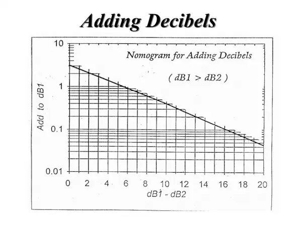
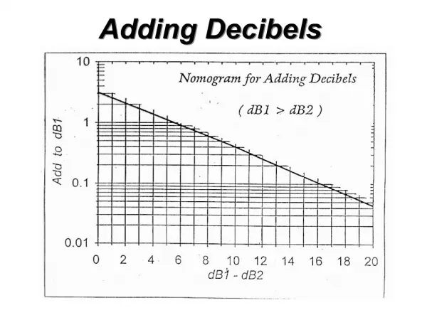
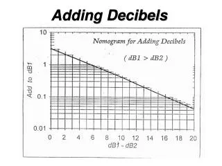
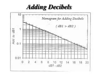
Decibels (dB) YdB = 10 log (x) where x is in power units (Watts) YdB = 10 log (10) = 10 dB YdB = 10 log (100) = 20 dB YdB = 10 log (20) = 13 dB YdB = 10 log (v2) for voltage across say 1W resistor YdB = 20 log (v) Decibels represent: 1. Level (absolute or relative) 2. Ratio (gain or loss)
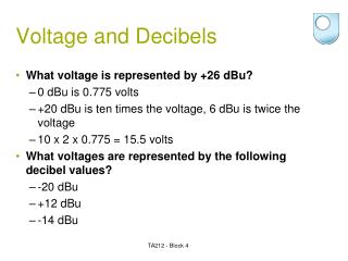
Decibels (Level) The RF output power level of a transmitter is specified in dBm (microwave radio) or dBw (mobile radio). Example: Microwave radio transmitter: 30 dBm (1 W) Mobile radio base station transmitter: 20 dBw (100 W) dBw = 10 log (P/1W) dBm =10 log (P/1mW) 1 Watt = 0 dBw 1 m Watt = 0 dBm
Examples of dBw and dBm 1 W 2 W 4 W 8 W 16 W 0 dBw 3 dBw 6 dBw 9 dBw 12 dBw 30 dBm 33 dBm 36 dBm 39 dBm 42 dBm
Decibels (Ratio) Po Vo Io Pi Vi Ii System dB = 10 log (Po/Pi) power ratio dB = 20 log (Vo/Vi) voltage ratio dB = 20 log (Io/Ii) current ratio
Noise Factor / Figure Linear System Si/Ni So/No Noise Factor (f) = (S/N) i / (S/N) o Noise Figure (NF) = 10 log ( f ) Note: Signal and Noise are in Power Unit
Two loudspeakers emit waves with l = 2.0 m. Speaker 2 is 1.0 m in front of speaker 1. What, if anything, must be done to cause constructive interference between the two waves? 1. Move speaker 1 backward (to the left) 0.5 m. 2. Move speaker 1 backward (to the left) 1.0 m. 3. Move speaker 1 forward (to the right) 1.0 m. 4. Move speaker 1 forward (to the right) 0.5 m. 5. Nothing. The situation shown already causes constructive interference.
Two loudspeakers emit waves with l = 2.0 m. Speaker 2 is 1.0 m in front of speaker 1. What, if anything, must be done to cause constructive interference between the two waves? 1. Move speaker 1 backward (to the left) 0.5 m. 2. Move speaker 1 backward (to the left) 1.0 m. 3. Move speaker 1 forward (to the right) 1.0 m. 4. Move speaker 1 forward (to the right) 0.5 m. 5. Nothing. The situation shown already causes constructive interference.