Download
1 / 7

E N D
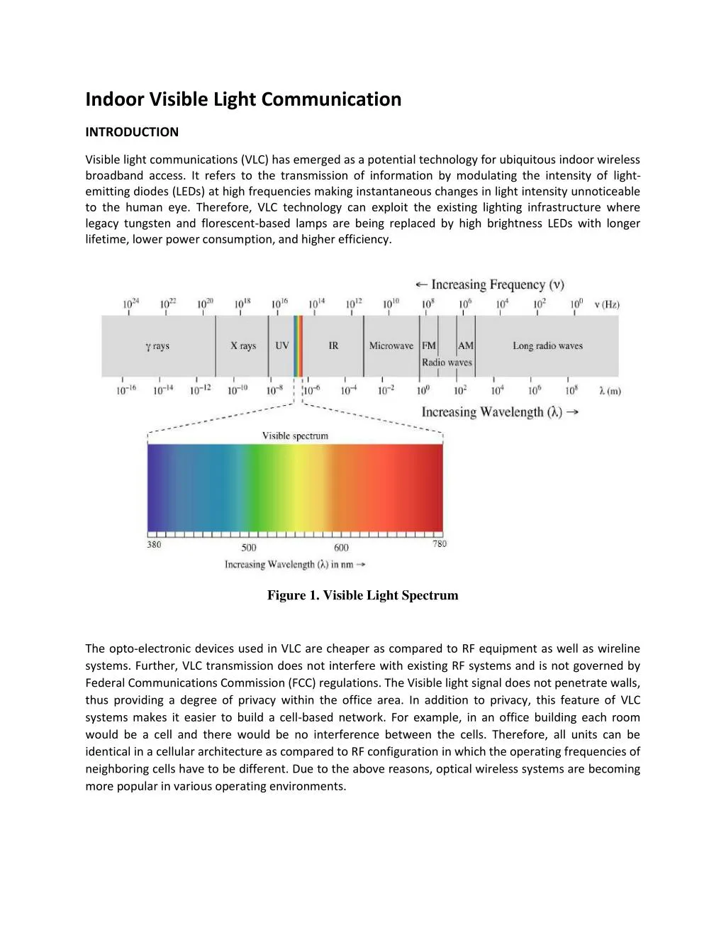
Indoor Visible Light Communication INTRODUCTION Visible light communications (VLC) has emerged as a potential technology for ubiquitous indoor wireless broadband access. It refers to the transmission of information by modulating the intensity of light- emitting diodes (LEDs) at high frequencies making instantaneous changes in light intensity unnoticeable to the human eye. Therefore, VLC technology can exploit the existing lighting infrastructure where legacy tungsten and florescent-based lamps are being replaced by high brightness LEDs with longer lifetime, lower power consumption, and higher efficiency. Figure 1. Visible Light Spectrum The opto-electronic devices used in VLC are cheaper as compared to RF equipment as well as wireline systems. Further, VLC transmission does not interfere with existing RF systems and is not governed by Federal Communications Commission (FCC) regulations. The Visible light signal does not penetrate walls, thus providing a degree of privacy within the office area. In addition to privacy, this feature of VLC systems makes it easier to build a cell-based network. For example, in an office building each room would be a cell and there would be no interference between the cells. Therefore, all units can be identical in a cellular architecture as compared to RF configuration in which the operating frequencies of neighboring cells have to be different. Due to the above reasons, optical wireless systems are becoming more popular in various operating environments.
MOTIVATION The number of personal computers and personal digital assistants for indoor use are rapidly growing in offices, manufacturing floors, shopping areas and warehouses. This will result in the need for flexible interconnection through the distributed or centralized data communication systems. [1] The traditional way to meet this requirement is to use wired physical connections. But, wired physical connections have some inherent problems, in setting up and in its expansion. Further, these need more space, time to setup, monetary investment in copper, maintenance etc. Wireless systems offer an attractive alternative. While the radio spectrum is limited, the demand for wireless data transmission keeps increasing. There is a pressing need for new kinds of wireless communication systems. Visible light communication (VLC) has been proposed as an alternative means of wireless communication. The idea is to modulate LEDs transmitting electromagnetic waves in the visible light frequencies to communicate between devices within the same room. HISTORY The VLC first developed by Dr. Alexander Graham Bell on 21st June, 1880. He had demonstrated a system which is capable of transmitting voice signals using sun light as a carrier and it was named as Photophone. The transmitter used sunlight reflected off a vibrating mirror to send voice signals. The receiver receives the light signal modulated with voice signal and demodulates it using selenium photo cell. The distance between the transmitter and receiver was around 213 meters in this demonstration. More new work started in 2003 at Nakagawa Laboratory, in Keio University, Japan, utilizing LEDs to convey information by noticeable light. Since then there have been countless study doings focused on VLC Figure 2. Photophone: Transmitter and Receiver [2]
INDOOR VLC SYSTEM Like any other communication system Visible light communication system also consists of three major components: 1.Optical Transmitter 2.Optical Receiver 3.Channel Figure 3. A VLC system A transmitter consists of an Information source, a driver circuit (which converts information signal into appropriate current variations to drive LED/LASER), LED/LASER, an optical antenna with other optical components such as lens and a tracking machine to direct the beam towards receiver side. On the receiver side, the receiving antennas (lens) collect all the power falling on it and focus it on the receiver detector. Detector converts optical signal to electrical signal, which will be demodulated to obtain the required message signal. Indoor atmosphere (channel for indoor VLC) is free of environmental degradation, such as mist, fog, particulate matter, clouds etc., indoor optical wireless systems encounter only free space loss and signal fading. Free Space Loss: It is that part of the transmitted power, which is lost or not captured by the receiver’s aperture Signal Fading: The reason for this is reception of signals via different paths by the receiver. Some of these interfere destructively (i.e. they are out of phase), so that the received signal power effectively decreases. This type of degradation is also known as multi-path signal fading.
Transmission Techniques Several transmission techniques are possible for indoor optical wireless systems; these techniques may be classified according to the degree of directionality of transmitter and receiver: 1.Directed beam (DBR) radiation: In DBR (Fig.4a) system, the optical beam travels directly without any reflection from the transmitter to the receiver. The optical wireless link using this technique is established between two fixed data terminals with highly directional transmitter and receiver at both ends of the link. Figure 4a. Directed beam (DBR) radiation 2.Diffuse (DFR) radiation: In DFR (Fig.4b) system, the transmitters send optical signals in a wide angle to the ceiling and after one or several reflections the signals arrive at the receivers. This is the most desirable configuration from a users’ point of view, since no alignment is required prior to use, and the systems do not require a line-of-sight path for transmission. In this configuration, the data rate depends on the room size and the reflection coefficients of the surfaces inside the room. Figure 4b. Diffuse (DFR) radiation
3.Quasi-diffuse (QDR) radiation (Cellular system): In QDR (Fig.4c) system, there is a base station (BS) with a relatively broad coverage made of passive or active reflector. The BS is usually mounted on the ceiling. The BS transmits (receives) the signal power to (from) the remote terminals (RTs). Figure 4c. Quasi-diffuse (QDR) radiation Modulation Techniques: In optical wireless communications, modulation takes place in two stages. First the transmitted information is coded as waveforms and then these waveforms modulate emitted visible light. Several modulation and detection schemes have been considered for use in optical wireless systems in the past. Most common schemes suitable for indoor optical wireless are the On-Off Keying (OOK), Pulse Modulation (PM) and Sub-carrier Modulation. OOK is the simplest technique to implement in wireless infrared transmission. Prior to transmission, the information is translated to a specific code such as Manchester, RZ, or NRZ codes, to get a stream of pulses. In OOK, a pulse is transmitted if the code bit is ‘one’ during a fixed time slot and a ‘zero’ is represented by the absence of the pulse during the time slot. Pulse Modulation (PM): Indoor optical wireless communication systems require modulation techniques, which make high-speed digital transmission possible with less average transmitter power. Higher average power efficiency can be achieved by employing pulse modulation schemes in which a range of time-dependent features of a pulse carrier may be used to convey information. Examples of such modulation schemes are: 1.PPM and its variants are widely considered as the best modulation techniques for power-limited intensity modulation with direct detection (IM/DD) communication systems. PPM has been widely used in optical communication systems. 2.Differential PPM (DPPM) is a simple modification of PPM that can achieve improved power and/or bandwidth efficiency in applications where low cost dictates the use of hard-decision detection, and multipath ISI is minimal (e.g., at low bit rates or in directed-LOS links). Sub-carrier Modulation High-speed single-carrier modulation schemes such as OOK and L-PPM are wide band and suffer from ISI due to multipath dispersion when the symbol rate exceeds
100 Mbps. When a bit stream modulates a single radio frequency, which is then further used to modulate optical carriers; the modulation is called single-sub-carrier modulation (SSM). ADVANTAGES Visible light communication has following advantages over other competing radio communication technologies such as Wi-Fi and cellular phone wireless communication: The first reason to consider is visible light’s frequency spectrum bandwidth, which ranges from 430 THz to 750 THz. The bandwidth is much larger than the radio frequency bandwidth, which ranges from 3 kHz to 300 GHz. There is no EMI. Visible light communication requires much less power compared to RF communication Visible light cannot penetrate through the walls, so Indoor Visible light communication is comparatively secure. Visible light usually poses no health hazards to human body and eyes. Light sources are everywhere and can be more efficiently used by increasing its simultaneous functionality by transmitting data in addition to lighting an area. DISADVANTAGES The most obvious is the fact that it will only work in places where there are electronic lights. The bandwidth of LED is limited and so are the data rates. It is LOS type of communication and thus blocking could interrupt the signal reception. Range of the communication link is limited due to the effect of turbulence, attenuation and background noise sources. High path losses leading to the requirement of higher transmission power levels, iii) multipath dispersion. Speed limitations of the opto-electronic devices. The interference induced by the artificial light sources. Shot noise induced by the background ambient light & aspects due to receiver noise. APPLICATION Lights in the visible spectrum are used everywhere, providing several opportunities to apply visible light communications. Some of the potential applications of visible light communication are: 1.Mobile-connectivity: By pointing a visible light at another device you can create a very high speed data link with inherent security. This overcomes the problems of having to pair or connect and provides a much higher data rate than Bluetooth or WiFi. 2.Positioning and communications: To obtain the position of a mobile user in indoors is challenging and VLC allows the transmission of positioning information from a lighting fixture so that a user knows their location in a building. There have been a number of schemes proposed that use either triangulation or proximity to a beacon or a combination to provide position estimation. 3.Illumination and communications: White LEDs can be used for both illumination and communications so that information can be broadcast within a room (LiFi) or transmitted via a
car headlight with the necessary illumination provided at the same time. This may be a wide area of application and there is considerable interest in building systems that do this. 4.Information display and communications: This is one of area of interest in VLC. Displays, such as signboards and indicator boards, are often fabricated from arrays of LEDs, and these can be modulated to broadcast the signboard information to a handheld terminal. This might find application in airports, museums and other environments where location dependent broadcast of data is required. CHALLENGES IN VLC SYSTEM: 1.Increasing data rate: White light LED’s manufactured using Phosphor is unable to support high data rate due to slow component of Yellow Phosphor. The simplest way of mitigating the low bandwidth is to block the phosphor component at the receiver by using a blue filter. Increase bandwidth using Blue filter is shown in [7]. It can also possible to improve the response by the use of bandwidth-efficient modulation schemes that take advantage of the high available signal to noise ratio. In addition by using Multi Input Multi Output (MIMO) using LED’s can get higher data rates. 2.Achieving a high electrical signal to noise ratio (SNR): The difficulty arises due to two reasons. Firstly, the SNR of an IM/DD system depends upon the square of the average power of the received optical signal. Secondly, in many environments there exists intense ambient infrared noise. 3.Eye Safety: Eye safety consideration puts limit on the amount of optical power that should be emitted by the transmitter, thus limiting the coverage of an optical wireless system. Both indoor and outdoor optical wireless systems can pose a hazard if LDs are operated at high output power. 4.Flickering: If the modulated optical carrier is changing with a very less frequency (<100Hz), then the user could see the change in the intensity of light with respect to time. This could be taken care if we use any of the sub-carrier modulation technique. 5.Uplink: VLC using illumination sources (LED’s) is naturally suited to broadcast applications, and providing an uplink to the distributed transmitter structures can be problematic. CONCOLUSION Indoor VLC offers the advantage of utilizing existing lighting infrastructure and visible light for indoor communication. It can provide both high speed and secure connection and the same time. There are a number of technical and regulatory challenges to be overcome, rapid technical progress is being made but the challenges of standardization will require cooperation and agreement from a number of different bodies. However, it is expected to provide an alternative means of wireless communication to accommodate the fast growing need for high speed communication. REFERENCES [1] Singh, Chaturi, et al. "A review of indoor optical wireless systems." IETE Technical Review 19.1-2 (2002): 3-17 [2] A. G. Bell, “Selenium and the Photophone,” in Nature vol. 22, ed, 1880, pp. 500-503