Download
1 / 65
730 likes | 994 Vues
Visible Light Communication - Tutorial -. 2008. 03. 17. Samsung Electronics. 802.15 DCN: 15-08-0114-00-0000. Storyline (Tutorial on Visible light communication). VLC introduction Identity : Definition, Differentiation from other standards History : VLC related activities in history

E N D
Visible Light Communication - Tutorial - 2008. 03. 17 Samsung Electronics 802.15 DCN: 15-08-0114-00-0000
Storyline(Tutorial on Visible light communication) • VLC introduction • Identity : Definition, Differentiation from other standards • History : VLC related activities in history • Motivation : LED infra, No regulation, No interference, Security… • LED introduction • LED technical evolution • LED market evolution • LED applications/advantages • LED modulation characteristics (B+Y, RGB, RCLED) • VLC potential application • VLC applicable services (Indoor, ITS, NFC) • VLC categorization (I2M, M2M, M2F) • VLC killer application • Indoor LBS • High-speed video streaming • VLC demo • Demo map • PI, IB, VL (including movie) • Summary • Technical issues (Oxford) • Source, Channel, Receiver • Link simulation • Link Experiment • System result • Technical challenge
Outline • Part 1 (Samsung) • VLC introduction • LED introduction • VLC potential application • Part 2 (Oxford univ.) • VLC components • Technical challenges
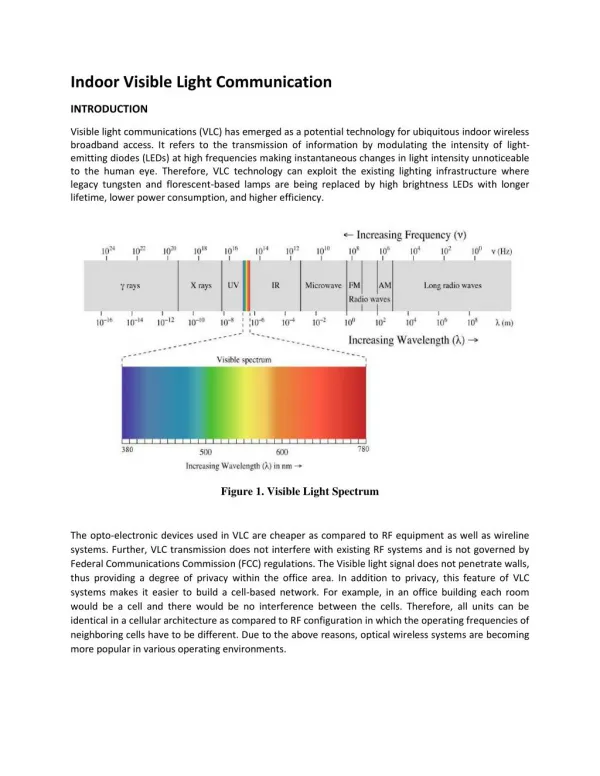
VLC introduction • VLC (Visible Light Communication) : New communication technology using “Visible Light”. • Visible Light : Wavelength between ~400nm (750THz) and ~700nm (428THz) • General Characteristic • Visibility : Aesthetically pleasing • Security :What You See Is What You Send. • Health :Harmless for human body and electronic devices • Unregulated :no room to use more radio frequency • Using in the restricted area :aircraft, spaceship, hospital • Eye safety
VLC history ~ 800 B.C. 405 B.C. 280 B.C. 1800s 1880 1900s Current Sunlight Heliograph Photophone By Bell Fire Beacon Fire Pharos Lighthouse Burning Kite In Battle Ship-to-ship Comm. Traffic Light /Signboard Light Lamp VLC LED
Morse code VLC history – Low speed • Information delivery through reflection by mirror (Heliograph) • The use of fire or lamp • Beacon fire, lighthouse, ship-to-ship comm. by Morse code • Traffic light : signal discrimination by color (Walk/Stop)
VLC history - Photophone • Bell’s Photophone (1880) • Optical source : sunlight • Externally modulation by vibrating mirror • Receiver : parabolic mirror with crystalline selenium cells • 700 ft (213m) sound transmission Excerpted from: The New Idea Self-Instructor edited by Ferdinand Ellsworth Cary, A. M. (Monarch Book Company, Chicago & Philadelphia, 1904) http://www.freespaceoptic.com/
IG-VLC 802.11 802.16 802.15.3c IG-THz Frequency band for VLC Low Frequency (Long wavelength) Coverage Mobility High Frequency (Short wavelength) Bandwidth Security 300MHz 300GHz 10GHz 3THz 428THz 750THz 300PHz RF IR visible UV 1mm 1m 3cm 100μm 700nm 400nm 1nm IrDA • IG-THz : contribution 15-07-0623-01, AT&T Labs discussed the Terahertz spectrum band which covers 300 GHz to 10 THz. • This mmWave WPAN will operate in the new and clear band including 57-64 GHz unlicensed band • The millimeter-wave WPAN will allow high coexistence (close physical spacing) with all other microwave systems in the 802.15 family of WPANs
VLC Characteristic HDR UWB 480M UWB 100M 802.11a 50M Data rate (bps) UFIR 802.11b 16M VLC FIR 4M Bluetooth VIR 115K ZigBee IR 1 2 3 6 11 20 50 Distance (m)
VLC Characteristic (mW/Mbps) Non-LOS Interference 1Mb/s, 1m 100 50 Mb/s, 50m Power consumption Speed 500 Mb/s, 3m 10 4 Mb/s, 1m LOS Security 1 10 100 1000 Distance Speed (m Mb/s) Directivity + Simplicity Optical connectivity saves power
VLC motivation • Communication community trend • Ubiquitous (Connect each other everywhere, every time) • Security • LED trend • LED technology (efficiency, brightness) • LED Cost • Environmental trend • Health • Energy saving • Intrinsic characteristic of VLC • Visibility • No interference / No regulation
Outline • Part 1 (Samsung) • VLC introduction • LED introduction • VLC potential application • Part 2 (Oxford univ.) • VLC components • Technical challenges
50 100 LED technical evolution • Performance and Price comparison 2003 LED 100 2005 LED 10 2010 Cost / Brightness ratio LED 1 Halogen Lamp Fluorescent Lamp 2015 HID (High-Intensity Discharge) LED Incandescent Lamp 150 0 Brightness / Power ratio Source: Credit Suisse, 2006.11.2
LED driver • Air Pollutions • UNFCCC (United Nations Framework Convention on Climate Change), Kyoto Protocol to the UNFCCC • (Dec. 1997)Decreasing CO2(10 k ton/year, 2002 at Korea) • Waste Materials & Environmental Hazards • RoHS (Restriction of the use of Certain Hazardous Substance): 1, July 2006. • Pb, Hg, Cd, Cr6+, Polybrominated biphenyls(PBB), • Polybrominated diphenyl eters(PBDE) • WEEE (Electrical and Electronic Equipment ) • Producer Responsibility • Energy saving effect • Electricity at Korea • 278 TWh(2002), 7.2 % of USA • 20% for Lighting:55.6 TWh • 50% saving by LED:27.8TWh • Energy Saving Effect: • 3 Nuclear Stations (1GW/day) • 2 B$/year Source: KOPTI (The Korea Photonics Technology Institute)
LED Market Forecast • LED market comparison with NAND, DRAM NAND, DRAM LED ※CAGR :15% 29 billion $ 29.2 billion $ DRAM LED 12.4 billion $ 11 billion $ 6.3 billion $ NAND LED LED 2006 2006 2002 2010 2017 Source: Deutsche Bank, 2007. 2
LED Applications LED application General Lighting Back Lighting Economical efficiency • Mobile Phone • Home applications digital device • TFT LCD TV • General Lighting • Task Lighting • Signal Lamp Communication Display • Exterior, interior display • Sign & Architecture display • LED screen • VLC • Mobile to Mobile • Infra to Mobile
LED modulation characteristics RCLED B + Phosphor LED R+G+B LED ~500 Mb/s ~40 Mb/s ~100 Mb/s
Outline • Part 1 (Samsung) • VLC introduction • LED introduction • VLC potential application • Part 2 (Oxford univ.) • VLC components • Technical challenges
1nm UV 380nm visible 780nm IR 100μm LAN 3cm RF 1m VLC application Peripheral Interface Bandwidth Security E-display Information Broadcast SAMSUNG e-book Contents Machine Sign Board ITS (Navigation) RF Prohibited Digital Hospital Banking Security In Plane Door Lock Visible LAN Coverage Mobility
Indoor application LED Illumination Infrastructure Ubiquitous Fixed-to-Infra Mobile-to-Infra Mobile-to-Fixed Mobile-to-Mobile Security
Outdoor application Outdoor advertising Traffic control Infrastructure Vehicle-to-Infra Vehicle-to-Vehicle
VLC application evolution LED penetration Sign ITS Mobile Display Illumination 10M Outdoor 100M Indoor 10M Indoor
Rx Rx Rx TRx Indoor navigation scheme
High-speed high-security connectivity What You See Is What You Send (WYSIWYS) E-Contents Vending Machine
High speed Low speed Demonstrations Tx, Rx (~30Mbps,Oxford Univ.) Mobile to Mobile (100Mbps,Samsung) LED array (~1Gbps, Keio Univ.) Infra to Mobile (10Mbps, Tamura Inc.) Sign board (10Mbps, Samsung) Music broadcasting (6Mbps, Oxford Univ.) Infra to Mobile(VLAN) (4Mbps, Samsung) Audio system (100kbps, Hongkong Univ.) Infra to Mobile, VLCC (Keio Univ., NEC, Toshiba, Sony, Matsushita, Casio etc. ) (4.8kbps, illuminations, visible light ID, sign board, applications based on JEITA)
VLC demonstration Infra to mobile Infra to mobile Mobile to mobile 100 Mb/s, 1m Bidirection 4 Mb/s, 3m Bidirection 20 Mb/s, 3m Unidirection
Mobile-to-mobile demo • What You See Is What You Send (WYSIWYS) • 120 Mb/s, 1m, Full duplex • File transfer and video streaming PDA/UMPC Spot @ 30 cm
D LS TS D LS TS D LS TS D LS Mobile-to-mobile (protocol) Transmitting Standby User alignment Device discovery Temporal blocking ( < 8 sec.) Beam guiding Start steaming Streaming end Primary Screen Link Secondary Screen
Mobile-to-mobile (Link performance) 120 Mb/s 240 Mb/s 320 Mb/s -log(BER)
Infra-to-mobile demo • RGB WDM transmission • 20 Mb/s, 3m, Uni-direction • Information broadcast from sign board
Infra-to-mobile (Link performance) Receiver (Silicon PD) Transmitter (RGB Sign-Board) Power Meter Data Rate = 10 Mb/s Data Rate = 20 Mb/s
Infra-to-mobile • TDMA-based P2MP • 4 Mb/s, 3 m, bi-direction • Secure indoor LAN
Infra-to-mobile (Link performance) • Downstream : White LED • Upstream : LD
Summary (Part 1) • VLC introduction • Identity • VLC history • Motivation • LED introduction • LED technical evolution • LED market forecast • LED application • LED modulation characteristics • VLC application • Application category • Indoor : Navigation, High-speed connectivity • Outdoor : ITS, Advertising • Demonstration • Mobile-to-mobile • Infra-to-mobile
Part 1 (Samsung) • VLC introduction • LED introduction • VLC potential application • Part 2 (Oxford univ.) • VLC components • Technical challenges
Visible Light Communications Dominic O’Brien, University of Oxford, dominic.obrien@eng.ox.ac.uk Contributions from Communications Group at Oxford
Overview Visible Light Communications Transmitter Channel Receiver Technical challenges Higher bandwidth Enabling mobility and reliability Conclusions
VLC Sources Blue LED & Phosphor Low cost Phosphor limits bandwidth Modulation can cause colour shift RGB triplet Higher cost Potentially higher bandwidth Potential for WDM Modulation without colour shift Single chip LED spectrum RGB LED spectrum
LED Modulation Opto-electronic response SPICE Model Rs = 0.9727 L = 33.342 nH Cs = 2.8 nF Cd = 2.567 nF tt = 1.09 ns Luxeon LED Measured LED small-signal bandwidth Page 5
Improvement of LED response Using blue-response only (blue filtering) ~130 ns ~25 ns Blue filtering Measured optical spectrum Measured impulse response • Issue: Only 10% of signal power is recovered Reducing SNR, link distance • LEDs with more blue energy [1] could be used to gain more filtered power, however the balance of white colour is shifted [1] Grubor, J., et al., "Wireless high-speed data transmission with phosphorescent white-light LEDs", Proc. ECOC 07 (PDS 3.6), pp. 1-2. ECO [06.11], 16-20 Sep. 2007, Berlin, Germany Page 10
Improvement of channel response Receiver equalisation Fitting falling time curve Equalization Measured LED impulse response Improved LED transmission BW Page 11
Improvement of LED bandwidth Pre-equalization: Resonant driving circuit A single resonant driving circuit Multiple resonant points (normalized) Page 12 Bandwidth of 16 LED source
Channel modelling Two propagation paths: Line of sight (LOS): strong paths calculated using the illumination patterns from LED arrays Diffuse: modelled by assuming the room is equivalent to an integrating sphere Channel impulse response is calculated for each point in the room Page 6
Room Power Distribution Assume 1% modulation of typical illumination power Typical receiver performance Conclusions Very high SNR available SNRmin = 38.50dB SNRmax = 49.41dB Modulation limited by source bandwidth
Noise sources Optical noise Daylight Generates DC photocurrent Blocked at receiver due to AC coupling Creates shot noise Other optical sources Fluorescent, Incandescent Creates electrical interference photocurrent harmonics Mitigated by Optical filtering Wavelength is in band of desired signal Electrical filtering
Optical receiver Receiver consists of Optical filter Rejects ‘out-of-band’ ambient illumination noise Lens system or concentrator Collects and focuses radiation Photodetector (or array of detectors) Converts optical power to photocurrent Incoherent detection Preamplifier (or number of preamplifiers) Determines system noise performance Post-amplifier and subsequent processing
Optical receiver: constant radiance theorem Optical ‘gain’ of receiver limited by required field of view Wi Ai AiWi<=AoWo AiWi<=Ao2p Wo Ao