Download
1 / 27
390 likes | 781 Vues
A Seminar on USB: Universal Serial Bus By Alok K. Watve M.Tech. (IT) 2 nd yr. Why USB? Much higher data rate compared to other data communication protocols (such as RS 232, parallel ports) USB 1.1 - 1.5 Mbps / 12 Mbps USB 2.0 - 1.5 Mbps / 12 Mbps / 480 Mbps

E N D
A Seminar onUSB: Universal Serial BusByAlok K. WatveM.Tech. (IT) 2nd yr. USB : Universal Serial Bus
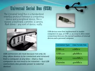
Why USB? • Much higher data rate compared to other data communication protocols (such as RS 232, parallel ports) • USB 1.1 - 1.5 Mbps / 12 Mbps • USB 2.0 - 1.5 Mbps / 12 Mbps / 480 Mbps • Supports plug and play. Hence easy to operate. • Allows large number of devices (theoretically 127) to be connected. • Support for real time audio/video data communication • Low cost USB : Universal Serial Bus
Different types of devices using USB - Storage devices (pen drives), CDROM drives - Digital cameras - Speakers, microphones - Printers, scanners - Keyboards, mice - Mobile phones USB : Universal Serial Bus
History • Developed by a group of seven companies - Compaq, Digital Equipment, IBM, Intel, Microsoft and Northern Telecom • USB 1.0 released in 23rd September 1996 supported two speeds • Low speed – 1.5 Mbps • Full speed – 12 Mbps • USB 1.1 released in 15th January1998 – No functional improvement. Clarification of certain timing parameters. • USB 2.0 released in 27th April 2000 • High speed – 480 Mbps • protocol extension USB : Universal Serial Bus
USB Architecture USB host : The root of the USB communication model with which all other USB devices communicate. USB function : USB devices like printers, cameras etc. which communicate with the host. A single physical device may have multiple functions. USB hub : a special device having a USB host or another hub on the upstream port and a number of USB devices (or hubs) on the downstream ports. USB follows tree topology in which host is the root. Each hub is a center of a local star. The tree can have at the most seven layers(tiers) including host tier. USB : Universal Serial Bus
USB topology Ref: Universal Serial Bus specification revision 2.0 April 27 2000 USB : Universal Serial Bus
Full speed Hub Speakers Low speed High speed Key board Digital camera Working of a typical USB system Sequence of events: 1. Bus enumeration 2. Configuration 3. Communication USB : Universal Serial Bus
Host 1 Keyboard Logical view of the system Host 2 Hub Digital Camera Speakers USB : Universal Serial Bus
Mechanical Specifications Deal with connector plugs, sockets and wires. Original USB specification defines only two types of connectors - 1. Series A – plugs are oriented upstream and receptacles are oriented downstream. 2. Series B – plugs are oriented downstream and receptacles are oriented upstream. Recently smaller versions of the plugs and sockets are designed and added to the specification. These plugs are to be used in portable devices like mobile phones. USB : Universal Serial Bus
Typical USB plugs and receptacles USB : Universal Serial Bus
Electrical specification • It defines the signaling, power distribution and physical layer specification. • USB uses NRZ I signaling with bit stuffing • USB cable contains 4 conductors. Two power conductors Vbus and GND. Two signal conductors D+ and D- • Pull-up resistors are used to detect any USB device automatically. They also determine the speed (low/full/high) at which the device operates. • For each speed, particular voltages at D+ and D- lines represent idle states. The resistor values are adjusted such that on ‘attach’ , D+ and D- will have the desired voltage levels USB : Universal Serial Bus
Example of automatic ‘attach’ detection for a full speed device: For a full speed device idle state is represented by D+ : High ( > 2.8V) D– : Low (<0.3V) Ref : http://www.beyondlogic.org/usbnutshell/usb2.htm USB : Universal Serial Bus
Example of automatic ‘attach’ detection for a low speed device: For a full speed device idle state is represented by D– : High ( > 2.8V) D+ : Low (<0.3V) Ref : http://www.beyondlogic.org/usbnutshell/usb2.htm USB : Universal Serial Bus
Power considerations USB devices can be either externally powered or bus powered. Bus powered devices with low power rating cannot draw more than 100 mA. Bus powered devices with high power rating can draw at the most 500mA.. Each device specifies its power rating (in terms of current) during configuration. If there is no bus activity for more than 3 ms, USB device goes in suspend mode during which it can draw up to 500μA. It is important for the host to keep track of power ratings of all the functions because if total power requirement goes beyond the driving capacity of the host, it will no longer be able to support all the devices. Host in such cases either rejects a particular device or puts some devices in suspend mode. USB : Universal Serial Bus
Frames Time slots are divided in frames. For high speed signaling the frame width is 125μs. For full speed signaling, the frame width is 1ms. Frames are especially important in interrupt mode data transfer. USB host transmits a ‘Start Of Frame’ (SOF) packet at the start of each frame. Although low speed device do not receive any SOF packet, they can see EOP (End Of Packet) signal on the bus, which acts as a reference for synchronization. SOF is used for two purposes : 1. It keeps host and functions synchronized with less than 0.05% error. 2. It prevents hosts from going into suspend mode in the absence of data. USB : Universal Serial Bus
USB protocol ClientSoftware Function USB system software USB logical device USB host controller USB Bus interface Logical communication Actual communication USB : Universal Serial Bus
USB data transfer types • Control transfer – used for Control messages e.g. SETUP • Interrupt transfer – error free delivery, guaranteed latency • Isochronous transfer –no error correction , only for FS/HS modes, guaranteed bandwidth, bounded latency • Bulk transfer – error-free delivery, no guarantee of latency or bandwidth, only for FS/HS modes Each logical pipe has an end point type that identifies the transfer type supported by the pipe. Each pipe is identified by an end point identifier (ENDP). Every device has to support a control pipe at address 0 (default pipe). Low speed devices can have 4 pipes. Full and high speed devices can have up to 16 pipes USB : Universal Serial Bus
Sync PID(8) EOP • USB transactions • Each transaction consists of : • A token packet • An optional data packet • A handshake packet • Token packet format • Data packet format • Handshake packet format Sync PID(8) Address(7) End point(4) CRC(5) EOP Sync PID(8) Data(0-8192) CRC(16) EOP USB : Universal Serial Bus
In addition to these three packets a special packet called Start Of Frame (SOF) is sent at the start of each frame. The format for SOF packet is as follows: High speed devices see an SOF packet with SAME frame number 8 times per frame (a frame consists of 8 micro frame). Sync Frame number(11) EOP USB : Universal Serial Bus
Split transactions and data rate translation • When a low/full speed device is connected to USB host through a hub, special transaction called ‘split transaction’ precedes any transaction between the host and the low speed device. • The sequence of events is as follows : • Start of Split token packet (host to hub) • FS/LS token • Data • Handshake (Complete split packet + handshake packet) USB : Universal Serial Bus
Ref: Universal Serial Bus specification revision 2.0 April 27 2000 USB : Universal Serial Bus
A complete taxonomy of packets and their PIDs PID 0000 is reserved. PID 1100 is used twice USB : Universal Serial Bus
Full speed Hub Speakers Low speed High speed Key board Digital camera Revisit the example of the USB system Sequence of events: 1. Bus enumeration 2. Configuration 3. Communication USB : Universal Serial Bus
Device configuration during bus enumeration • Host reads several descriptors from the device. Commonly used descriptors are: • Device descriptors(Only one for each device) • Configuration descriptor(can be more than one) • Interface descriptors (can be more than one per interface , a device can have multiple interfaces) • Endpoint descriptors (One for each endpoint) • String descriptors (Description of device in human readable form) • These descriptors give host all the information needed to configure a device. Some parameters of the descriptors are given by the USB-Implementer’s Forum USB : Universal Serial Bus
Recent developments • USB OTG(on-the-go) • Point to point connection • Low power consumption • Simplified cabling more connectivity options • Wireless USB USB : Universal Serial Bus
References • Universal Serial Bus Specification – revision 2.0 – April 2000 • http://www.beyondlogic.org/usbnutshell/ • http://www.sss-mag.com/usb.html • http://www.usbdeveloper.com/ • USB implementer’s forum – www.usb.org • www.semiconductors.philips.com/markets/connectivity/wired/usb/products/otg/tutorial/ USB : Universal Serial Bus
Questions ? USB : Universal Serial Bus