Download
1 / 38
520 likes | 1.62k Vues
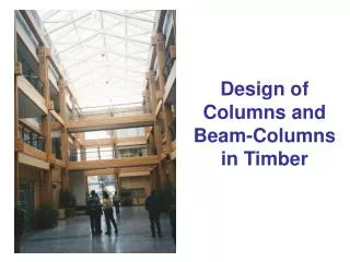
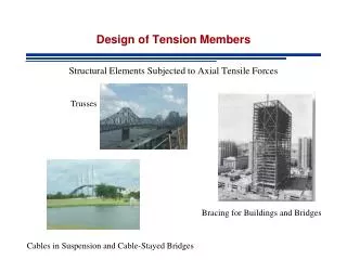
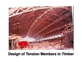
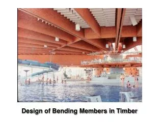
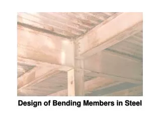
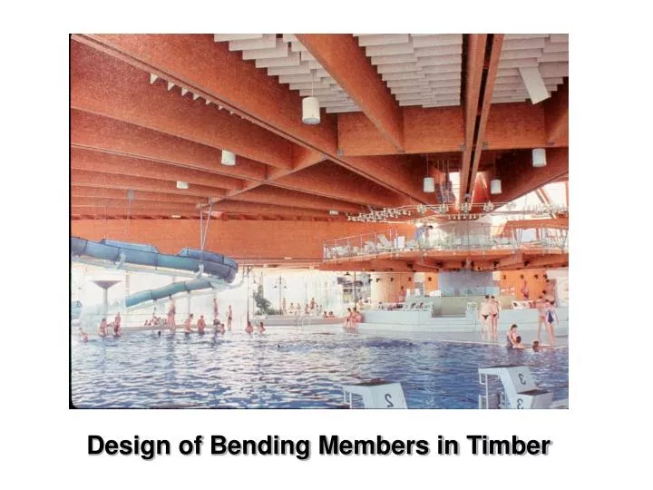
Design of Bending Members in Timber. An Example of Timber Beams. What can go wrong ?. TIMBER BEAMS: Bending failure Lateral torsional buckling Shear failure Notch failure Bearing failure Excessive deflections. Bending Strength . Linear elastic stresses. y. M. Design Equation:.

E N D
What can go wrong ? TIMBER BEAMS: • Bending failure • Lateral torsional buckling • Shear failure • Notch failure • Bearing failure • Excessive deflections
Bending Strength Linear elastic stresses y M Design Equation: Where Fb is the characteristic bending strength For timber it is Fb = fb (KDKHKSbKT)
Bending failure in compression • Only likely for very high grade material • Benign failure mode
Logging bridge near Pemberton, BC Glulam I-beam
Bending failure in tension • Most likely failure mode • Brittle • Combination of tension and shear, although tension fracture is the initiating mode
Lateral torsional buckling Bending capacity Mr = φ Fb S KZb KL where φ = 0.9 and Fb = fb (KD KH KSb KT )
Glued-laminated beams better laminations 20f-E and 24f-E grades
better laminations Glued-laminated beams 20f-EX and 24f-EX grades
Elastic buckling: Mcr = π / Le √(G J E Iy ) Lateral bending stiffness Torsional stiffness y y Δx x Δy θ x x y y Lateral torsional buckling of timber beams Le Note: The warping stiffness for rectangular shapes is small compared to the torsional and bending stiffness
Mu Mr = φ Fb S KZb Mr = φ Fb S KZb KL material failure combination of material failure and lateral torsional buckling elastic lateral torsional buckling Capacity of a timber beam subject to lateral torsional buckling Mr Le
Lateral torsional buckling factor KL KL 1.0 KL = 1 KL = 1 – 1/3 (CB / CK)4 0.67 practical limit 0.5 KL = (0.65 E KSE KT) / (CB2 Fb KX) CK = ( 0.97 E KSE KT / Fb )0.5 0 CB 0 10 20 30 40 50 Slenderness ratio CB = ( Le d / b2 )0.5
d b Prevention of lateral torsional buckling < 610 mm KL = 1.0 when lateral support is provided as shown < 610 mm < 8d
A τ y d τmax = V(0.5A)(d/4) (bd3/12)b =1.5 V/A N.A. b Shear stress in a beam
Shear in a timber beam As σv(max) Vr = φ Fv 2/3 A KZv where φ = 0.9 and Fv = fv (KD KH KSv KT ) σv(avg) σv(max) = 1.5 σv(avg) = 1.5 V / A
UNBC Prince George, BC
This part of the load transferred in direct compression • Direct compression transfer of loads in the end zones reduces the total shear force to be carried. 45o critical section Shear failures • One of the very weak properties of wood • Shrinkage cracks often occur at the ends of beams in the zone of maximum shear stress
Shear design of glulam beams A simple approach for beams where the volume < 2.0 m3: Vr = φ Fv 2/3 A KN where φ = 0.9 and Fv = fv (KD KH KSv KT ) KN = notch factor (see next section) For larger beams this is usually quite conservative and a more sophisticated approach is used (see clause 6.5.7.3)
Notch factor for Glulam beams dn d dn e KN = ( 1 – dn/d )2 For e > d : KN = ( 1 – dn/d ) For e < d : KN = 1 – dne/[d(d – dn)]
Notch effect in sawn lumber • For notches on the tension side of supports (sawn lumber) • In new code: Reaction calculation NEW !! • Fr = Ft A KN • = 0.9 • Ft = ft (KD KH KSt KT) • where ft = specified reaction force strength = 0.5 MPa for sawn lumber • KSt = 1.0 for dry and 0.7 for wet service conditions • A = gross cross-section area • KN = notch factor Area A
d1 e d dn Notch factorKN Based on Fracture Mechanics theory
Not only compression perpendicular to grain but also tension of the fibres along edges compression perpendicular to grain tension of fibres along the edges Bearing failure in a timber beam • The “soft” property of wood • Often governs
< 150mm no high bending stress > 75mm Bearing factor Bearing resistance Ab Qr = Fcp Ab KZcp KB = 0.8 Fcp = fcp (KScp KT)
Bearing resistance (double bearing) Ab2 Abavg= 0.5(Ab1 +Ab2) but ≤ 1.5 Ab1 Ab1 45 deg Qr = (2/3) Fcp Abavg KZcp KB = 0.8 Fcp = fcp (KD KScp KT)
Deflections • A serviceability criterion • Avoid damage to cladding etc. (Δ ≤ L/180) • Avoid vibrations (Δ ≤ L/360) • Aesthetics (Δ ≤ L/240) • Use unfactored loads • Typically not part of the code • Δ