Download

1 / 53
580 likes | 1.58k Vues
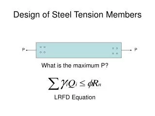
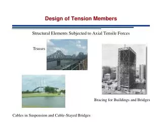
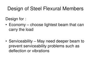
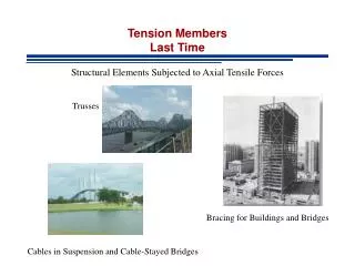
Design of Tension Members. Structural Elements Subjected to Axial Tensile Forces. Trusses. Bracing for Buildings and Bridges. Cables in Suspension and Cable-Stayed Bridges. LAST TIME. Design of Tension Members Tables for the Design Threaded Rods and Cables. LRFD. max. LRFD. ASD. min.

E N D
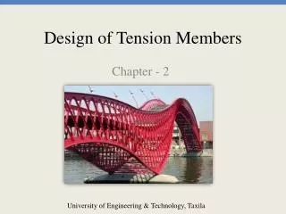
Design of Tension Members Structural Elements Subjected to Axial Tensile Forces Trusses Bracing for Buildings and Bridges Cables in Suspension and Cable-Stayed Bridges
LAST TIME • Design of Tension Members • Tables for the Design • Threaded Rods and Cables
LRFD max LRFD ASD min min max ASD etc Design of Tension Members LAST TIME • Objective • Find a member with adequate gross and net areas • Find a member that satisfies L/r<300 • Does not apply to cables and rods Available Strength (Nominal Resistance) Required Strength
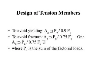
Design of Tension Members LAST TIME Determine required Area LRFD To prevent yielding To avoid fracture Yielding controls if
Design of Tension Members LAST TIME • Determine required Area ASD To prevent yielding To avoid fracture Yielding controls if
LRFD - Example LAST TIME Tension member with a length 5’-9” resists D=18 kips and L=52 kips Select a member with rectangular cross section, A36 steel and one line 7/8” bolts Step 1: Required Strength Step 2: Required Areas
LRFD - Example LAST TIME Tension member with a length 5’-9” resists D=18 kips and L=52 kips Select a member with rectangular cross section, A36 steel and one line 7/8” bolts Step 3: Plate Selection based on Ag Try thickness t = 1 in Choose PL 1 X 3-1/2 See Manual pp1-8 for availability of plate products
LRFD - Example LAST TIME Tension member with a length 5’-9” resists D=18 kips and L=52 kips Select a member with rectangular cross section, A36 steel and one line 7/8” bolts Step 4: Check Effective Area OK
LRFD - Example LAST TIME Tension member with a length 5’-9” resists D=18 kips and L=52 kips Select a member with rectangular cross section, A36 steel and one line 7/8” bolts Step 4: Check Slenderness OK
ASD - Example LAST TIME Tension member with a length 5’-9” resists D=18 kips and L=52 kips Select a member with rectangular cross section, A36 steel and one line 7/8” bolts Step 1: Required Strength Step 2: Required Areas
ASD - Example LAST TIME Tension member with a length 5’-9” resists D=18 kips and L=52 kips Select a member with rectangular cross section, A36 steel and one line 7/8” bolts Step 3: Plate Selection based on Ag - Same as LRFD Try thickness t = 1 in Choose PL 1 X 3-1/2 See Manual pp1-8 for availability of plate products
ASD - Example LAST TIME Tension member with a length 5’-9” resists D=18 kips and L=52 kips Select a member with rectangular cross section, A36 steel and one line 7/8” bolts Step 4: Check Effective Area OK
LRFD - Example LAST TIME Tension member with a length 5’-9” resists D=18 kips and L=52 kips Select a member with rectangular cross section, A36 steel and one line 7/8” bolts Step 4: Check Slenderness OK
Angles as Tension Members LAST TIME • Must have enough room for bolts (if bolted connection) • Space is a problem if 2 lines of bolts in a leg • Usual fabrication practice – standard hole location Manual pp 1-46
Example LAST TIME • Select and unequal-leg angle tension member 15 feet long to resist a service dead load of 35 kips and a service live load of 70 kips. Use A36
Angle - Example LAST TIME Step 1: Required Strength Step 2: Required Areas
Angle - Example LAST TIME Step 3: Angle Selection based on Ag Two lines of bolts, therefore min. length of one leg = 5 in see table Choose L6x4x1/2 A=4.75, rmin=0.864 See Manual pp1-42
Angle - Example LAST TIME Step 4: Check Effective Area Length of connection not known 4 – bolts in direction of load U=0.8 NG
Angle - Example LAST TIME Step 3: Angle Selection based on Ag – TRY NEXT LARGER Two lines of bolts, therefore min. length of one leg = 5 in see table Choose L5 x 3-1/2 x 5/8 A=4.92, rmin=0.746 See Manual pp1-42
Angle - Example LAST TIME Step 4: Check Effective Area Length of connection not known 4 – bolts in direction of load U=0.8 NG
Angle - Example LAST TIME Step 3: Angle Selection based on Ag – TRY NEXT LARGER Two lines of bolts, therefore min. length of one leg = 5 in see table Choose L8 x 4 x 1/2 A=5.75, rmin=0.863 See Manual pp1-42
Angle - Example LAST TIME Step 4: Check Effective Area Iterative Process Length of connection not known 4 – bolts in direction of load U=0.8 OK
Example • Select and unequal-leg angle tension member 15 feet long to resist a service dead load of 35 kips and a service live load of 70 kips. Use A36
Example – Using Tables Step 1: Required Strength Step 2: Choose L based on Pu Choose L6x4x1/2 A=4.75, rmin=0.980 See Manual pp 5-15
Angle - Example Step 3: Check Effective Area Length of connection not known 4 – bolts in direction of load U=0.8 NG
Angle - Example Shape did not work because table values are for Ae/Ag=0.75 In this problem Ae/Ag=3.1/4.75 = 0.6526 Enter table with adjusted Pu as
Example – Using Tables Step 4: Choose L based on ADJUSTED Pu Choose L8x4x1/2 A=5.75, rmin=0.863 See Manual pp 5-14
Angle - Example Step 5: Check Effective Area Length of connection not known 4 – bolts in direction of load U=0.8 OK
Tension Members in Roof Trusses • Main supporting elements of roof systems where long spans are required • Used when the cost and weight of a beam would be prohibitive • Often used in industrial or mill buildings
Pin Hinge Tension Members in Roof Trussed Supporting walls: reinforced concrete, concrete block, brick or combination
Tension Members in Roof Trusses Sag Rods are designed to provide lateral support to purlins and carry the component of the load parallel to the roof Located at mid-point, third points, or more frequently
Tension Members in Roof Trusses Bottom Chord in tension Top Chord in compression Web members: some in compression some in tension Wind loads may alternate force in some members
Tension Members in Roof Trusses Chord Members are designed as continuous Joint rigidity introduces small moments that are usually ignored Bending caused by loads applied directly on members must be taken into account
Tension Members in Roof Trusses Working Lines Intersect at the Working Point in each joint • Bolted Truss: Working Lines are the bolt lines • Welded Truss: Working Lines are the centroidal axes of the welds • For analysis: Member length from working point to working point
Tension Members in Roof Trusses Bolted trusses Double Angles for chords Double Angles for web members Single Gusset plate
Tension Members in Roof Trusses Welded trusses Structural Tee shapes are used in chords Angles are used in web members Angles are usually welded to the stem of the Tee
Tension Members in Roof Trusses Welded trusses Structural Tee shapes are used in chords Angles are used in web members Angles are usually welded to the stem of the Tee
Example Select a structural Tee for the bottom chord of the Warren roof truss. Trusses are welded and spaced at 20 feet. Assume bottom chord connection is made with 9-inch long longitudinal welds at the flange. Use A992 steel and the following load data (wind is not considered) Purlins M8x6.5 Snow 20 psf horizontal projection Metal Deck 2 psf Roofing 4 psf Insulation 3 psf
Step 1 – Load Analysis DEAD (excluding purlins) Deck 2 psf Roof 4 psf Insulation 3 psf Total 9 psf Total Dead Load = 9(20) = 180 lb/ft 20ft 180(2.5)=450 lb 180(5)=900 lb ……
Step 1 – Load Analysis PURLINS M8x6.5 Purlin Load = 6.5(20) = 130 lb 20ft 130 lb 130 lb ……
Step 1 – Load Analysis SNOW Snow Load = 20(20) = 400 lb/ft 20ft 400(2.5)=1000 lb 400(5)=2000 lb ……
Step 1 – Load Analysis Dead Load of Truss Assume 10% of all other loads End Joint 0.1(9(20)(20)+130+1000)=158 lb Interior Joint 0.1(900+130+2000)=303 lb 158 lb 303 lb ……
Step 1 – Load Analysis 450+130+158 = 738 lb 900+130+303 = 1333 lb …… D 1000 lb 2000 lb S
Step 2 – Required Force 1.2(0.74) + 1.6(1) = 2.48 kips 1.2(1.33)+1.6(2)= 4.8 kips ……
Step 2 – Required Force Method of Sections
Step 4: T Selection based on Ag Choose MT5x3.75 A=1.10 in2 See Manual pp1-68