Download
1 / 8
90 likes | 302 Vues
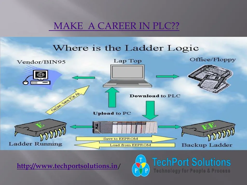
PLC : <br>The memory unit of a PLC is the registry where the programs are stored. The fundamental unit of memory is the word. Words are made up of bits. A bit is a single piece of data. It contains information on only two states (ON/OFF or YES/NO). Longer words contain more information within. Programs are combination of words that produce control logic.<br>To operate the PLC system there is a need for it to access the data to be processed and instructions, that is, the program, which informs it how the data is to be processed. Both are stored in the PLC memory for access during processing.<br>BASIC PLC HARDWARE ARCHITECTURE<br> <br>The PLC consists of the following components:<br>• The processor module (CPU)<br>• Memory<br>• The power supply,<br>• and the Input/output modules.<br><br><br>PLC MEMORY : <br>The memory unit of a PLC is the registry where the programs are stored. The fundamental unit of memory is the word. Words are made up of bits. A bit is a single piece of data. It contains information on only two states (ON/OFF or YES/NO). Longer words contain more information within. Programs are combination of words that produce control logic.<br>To operate the PLC system there is a need for it to access the data to be processed and instructions, that is, the program, which informs it how the data is to be processed. Both are stored in the PLC memory for access during processing.<br>ROM and RAM are the most common types of memory used in PLCs.<br>READ ONLY MEMORY (ROM): stores programs and data and cannot be changed after the memory chip has been manufactured. ROM memory is non-volatile, meaning that its contents will not be lost if power is lost. ROM is used by the PLC for the operating system.<br>RANDOM ACCESS MEMORY (RAM): is designed so that information can be written into or read from the memory. RAM is used as a temporary storage area of data that may need to be quickly changed. RAM is volatile, meaning that the data stored in RAM will be lost if power is lost. A battery backup is required to avoid losing data in the event of a power loss<br><br>INPUT OUTPUT MODULES : <br> I/O modules physically connect to field devices, that is they provides the interface between the system and the outside world, allowing for connections to be made through input/output channels to input devices. Since there are different types of input and output devices, the process determines the type of input or output module selected, digital or analog.<br>Input gives the controller real time status of variable in the form of real world signals. These variables can be analog, register or discrete. Typical analog inputs can be from thermocouples, RTDs, flow, pressure, and temperature transmitters. These inputs are transmitted over the I/O bus to the central processor unit after being converted into digital data. The input module is entrusted with the operation of converting electrical signals flowing in from input field devices like push buttons to electrical signals that the PLC can understand. Examples of input modules include limit switches, proximity switches and push buttons, photo sensors, and temperature sensors,motion control or high-speed counters.<br>

E N D
MAKE A CAREER IN PLC?? http://www.techportsolutions.in/
DEVELOPING AND DESIGNING HMI&DCS/PLC SYSTEMS Design and configuration of PLC systems within Control systems Lab provide students both from Control and Computer Science Departments with an opportunity to learn selection, programming, operation, and capabilities/limitations of programmable logic controllers and human machine interface (HMI) software based on networked PC to provide necessary connection between human user (Operator, process engineer ) and PLC integrated with plant and process data. http://www.techportsolutions.in/
DEVELOPING AND DESIGNING PLC http://www.techportsolutions.in/
BASIC PLC HARDWARE ARCHITECTURE • The PLC consists of the following components: • The processor module (CPU) • Memory • The power supply, • and the Input/output modules. http://www.techportsolutions.in/
PLC MEMORY The memory unit of a PLC is the registry where the programs are stored. The fundamental unit of memory is the word. Words are made up of bits. A bit is a single piece of data. It contains information on only two states (ON/OFF or YES/NO). Longer words contain more information within. Programs are combination of words that produce control logic. To operate the PLC system there is a need for it to access the data to be processed and instructions, that is, the program, which informs it how the data is to be processed. Both are stored in the PLC memory for access during processing. http://www.techportsolutions.in/
INPUT OUTPUT MODELS I/O modules physically connect to field devices, that is they provides the interface between the system and the outside world, allowing for connections to be made through input/output channels to input devices. Since there are different types of input and output devices, the process determines the type of input or output module selected, digital or analog. http://www.techportsolutions.in/
http://www.techportsolutions.in/ OUR CLIENTS : For Your Reference !! • * * Kranti SSK , Kundal • * * VishwasSSk,Shripur • * * VitthalSSK,Pandharpur • ** VitthalraoShindeSSk,Madha • ** ManjaraSSk,LatureBaramatiAgro,Shetphalgadhe • ** Baramati Agro ,Kannad • * * SaswadMali,Malinagar CONTACT : Sales: +91 738 710 0147Tech Support: +91 738 710 0146 Office: 020 65330999 Email: info@techportsolutions.in